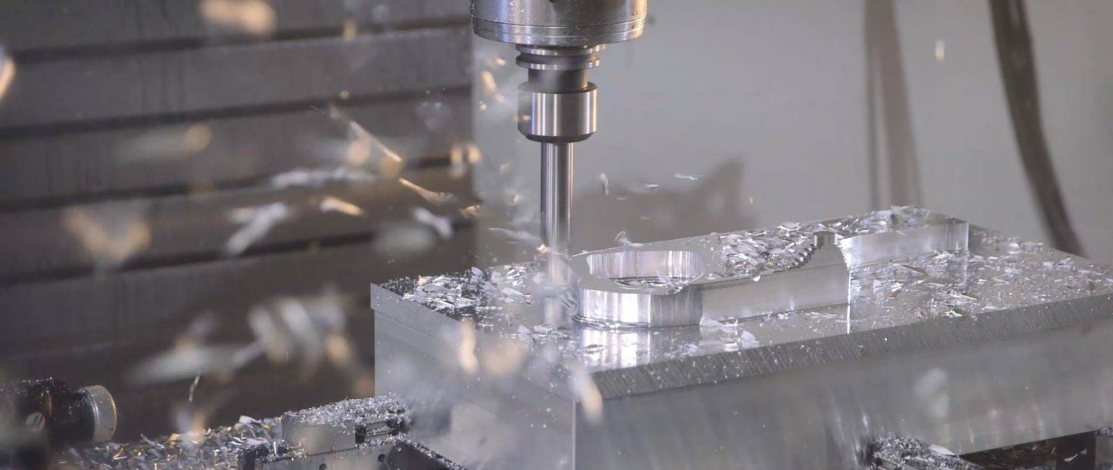
CNC machining capabilities define the range of parts, tolerances, materials, and complexities that modern computer-controlled cutting equipment can produce. Understanding these capabilities is essential for selecting the right manufacturing process for your project.
This guide provides a complete, fact-based overview of standard CNC machining capabilities based on industry practices and machine tool specifications. All information is derived from publicly available machine manufacturer data and industry standards (e.g., ISO 2768, ASME B46.1).
01Core Capabilities at a Glance
CNC machining can produce parts from virtually any rigid material, with dimensional tolerances as tight as ±0.0002 inches (±0.005 mm), surface finishes down to 8 microinches Ra, and feature sizes from 0.020 inches (0.5 mm) up to several feet. It supports 3‑axis, 4‑axis, and 5‑axis simultaneous motion, enabling complex geometries including undercuts, freeform surfaces, and deep cavities.
02Material Capabilities
CNC machining works with over 50 engineering materials. The most common families include:
Metals: Aluminum (6061, 7075), stainless steel (303, 304, 316), brass, copper, titanium (Grade 5), tool steels, and Inconel.
Plastics: ABS, polycarbonate,nylon, Delrin (acetal), PEEK, PTFE, and acrylic.
Composites & others: Carbon fiber (machinable grades), fiberglass, and wood.
Case example: A medical device company needed 500 hip implant trial components from titanium alloy (Grade 5). Using 5‑axis CNC milling, the manufacturer held ±0.0005” tolerances on all critical mating surfaces, with no secondary finishing required. The parts passed all functional tests.
03Dimensional & Tolerance Capabilities
Source ranges: Haas Automation, DMG MORI, Citizen Machinery – typical published specs.

Important: Tighter tolerances (e.g., ±0.0001”) are possible but increase cost and lead time. For most applications, the standard ±0.005” (±0.13 mm) is sufficient and cost‑effective.
04Geometric Capabilities
Minimum hole diameter: 0.020” (0.5 mm) – standard drilling; 0.004” (0.1 mm) with EDM (electrical discharge machining, a complementary process).
Minimum internal corner radius: Equal to cutter diameter/2. For a 1/8” end mill, corner radius is 0.0625”. To achieve sharp internal corners, design a relief or use wire EDM.
Maximum depth‑to‑diameter ratio for milling: 4:1 for standard tools; 10:1 with specialized long‑reach tools (reduces feed rate).
Threading: Unified, metric, pipe threads from #0 (0.060”) to 2.5” diameter. Internal threads down to 1.5x diameter depth standard.
Undercuts & dovetails: Possible with T‑slot cutters or lollipop mills, typically up to 0.5” depth per pass.
05Surface Finish Capabilities
As‑machined surface finish ranges from 32 to 125 microinches Ra (0.8 – 3.2 µm). With proper tooling and speeds, finishes of 16 microinches Ra (0.4 µm) are achievable. Finer finishes (8 µin Ra) require a secondary process like grinding or lapping.
Case example: An automotive prototyping shop produced intake manifold runners from 6061 aluminum. Using a ball‑nose end mill with 0.005” stepover, they achieved a 20 µin Ra finish on curved surfaces – sufficient for airflow testing without polishing.
06Complexity & Multi‑Axis Capabilities
3‑axis: Ideal for prismatic parts (boxes, brackets, plates) with flat faces and vertical walls.
4‑axis (adding a rotary table): Enables parts with features around a cylinder (cam lobes, helical gears, ports).
5‑axis (simultaneous motion): Allows undercuts, contoured surfaces, and complex aerospace or medical implants. Reduces setups from 5‑6 to 1‑2, improving accuracy.
Real‑world scenario: A drone manufacturer needed a one‑piece armature with integrated bearing pockets and cooling fins on five sides. With 5‑axis machining, all features were cut in a single clamping – eliminating alignment errors from multiple setups.
07Production Volume Capabilities
Prototyping (1‑10 units): Lead time as fast as 24 hours for simple parts. No tooling cost.
Low‑volume production (10‑500 units): Most economical per part due to minimal fixturing.
Medium volume (500‑2000 units): Still viable; consider alternative processes like casting above 2000 units for very high volume, but CNC remains flexible for design changes.
Cost factor: Setup time dominates for small batches. For a simple bracket (10 min machine time), setup might be 30 min – so cost per part is high for 1 piece but drops sharply by 50 pieces.
08Limitations (What CNC Cannot Do)
Internal sharp corners (without relief holes or EDM).
Very deep ribs (>10x width) – prone to tool deflection and chatter.
Extreme aspect ratio holes (>20:1 depth:diameter) – use EDM or gun drilling.
Soft, flexible materials (silicone, rubber) – require molding or casting.
True mirror finishes directly from milling – need post‑processing.
09How to Verify a Supplier’s Capabilities
Before ordering, request:
1. Machine list – Look for 5‑axis or high‑precision models (e.g., with glass scales).
2. Inspection reports – CMM (coordinate measuring machine) data showing actual tolerances.
3. Material certifications – Mill test reports for traceability.
4. Sample parts – Ask for a representative part from your drawing.
Actionable recommendation: Always provide a 2D drawing with critical tolerances and surface finish callouts alongside your 3D CAD. This ensures the shop quotes their real capability, not just the CAD model’s nominal dimensions.
10Key Takeaway & Next Steps
CNC machining capabilities today cover nearly any rigid material, tolerances suitable for aerospace and medical implants, and complex geometries through 5‑axis technology. For 95% of mechanical parts, standard CNC (3‑axis + lathe) with tolerances of ±0.005” will succeed at the lowest cost.
To get your part made correctly:
Define your minimum required tolerance – do not over‑specify.
Design accessible features – avoid impossible internal corners.
Match material to function – aluminum for speed, steel for strength.
Request capability documentation from your supplier.
By understanding these core CNC machining capabilities, you can design parts that are both functional and economical to produce. When in doubt, consult the machine specifications or industry standards (ISO 2768‑mk for general tolerances) before finalizing your design.