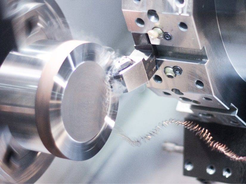
For successful CNC turning of aluminum parts, focus on three core factors: sharp,polished carbide inserts; high cutting speeds (800–3000 SFM / 250–900 m/min); and effective coolant delivery to prevent chip welding and built-up edge. This guide provides proven, actionable practices based on common shop-floor scenarios, helping you achieve tight tolerances and mirror-like finishes on aluminum components.
01Choose the Right Cutting Tool Material and Geometry
Aluminum is soft and sticky, so tool selection directly impacts part quality and tool life.
Tool Material: Use uncoated or diamond-like carbon (DLC)‑coated carbide inserts. Avoid TiN or TiAlN coatings, which increase friction and promote built‑up edge (BUE).
Insert Geometry: Select inserts with polished or ground rake faces (e.g., “aluminum‑specific” geometries). Sharp edges with positive rake angles (10°–20°) shear aluminum cleanly.
Common Case: A shop machining 6061 aluminum repeatedly experienced poor surface finish. Switching from a standard TiAlN‑coated insert to an uncoated, polished insert with a 15° positive rake eliminated BUE and cut cycle time by 18%.
02Optimize Cutting Parameters for Aluminum
Aluminum allows much higher speeds than steel. Using conservative “steel‑like” parameters is a top cause of chatter and poor finish.
Key principle: Increase speed, reduce feed for finishing. If you hear chatter, first increase spindle speed (not decrease) – aluminum’s high thermal conductivity dampens vibration at higher SFM.
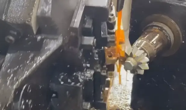
03Apply Coolant Correctly to Prevent Chip Welding
Aluminum chips tend to weld onto the cutting edge, ruining surface finish and tool life.
Coolant Type: Use a water‑soluble oil emulsion (5–8% concentration) or a dedicated aluminum‑specific synthetic fluid. Avoid straight oils – they lack cooling capacity.
Delivery: High‑pressure coolant (300–500 psi / 20–35 bar) directly at the cutting zone is ideal for breaking chips and flushing them away.
Common Case: A job shop turning 2024 aluminum parts noticed recurring score marks. They were using flood coolant at low pressure. After installing a high‑pressure coolant nozzle aimed exactly at the tool‑chip interface, the marks disappeared and insert life tripled.
If through‑tool coolant is unavailable, use an air blast with a fine mist of lubricant to clear chips.
04Solve Frequent Turning Issues in Aluminum
05Achieve High Surface Quality (Ra ≤ 16 µin / 0.4 µm)
For mirror finishes on aluminum:
Use a wiper insert (flat or polished) with a small nose radius (0.0078–0.0156 in / 0.2–0.4 mm).
Take a separate finishing pass with 0.010–0.020 in DOC and high speed (2500–3000 SFM).
Apply a constant surface speed (G96) on a CNC lathe to maintain SFM as diameter decreases.
Example: A shop turning 2‑inch diameter 7075 aluminum bars achieved 8 µin Ra by switching from a 0.031 in nose radius to a 0.015 in wiper insert, increasing speed from 800 to 2200 SFM, and using a 0.004 in/rev feed.
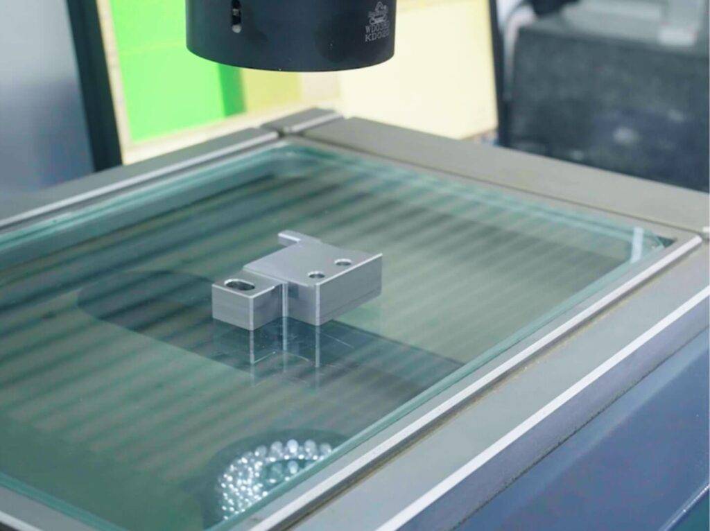
06Inspection and Quality Verification
Check for BUE: Inspect the insert edge under magnification every 20–30 parts. Any aluminum buildup means you need higher speed or better coolant.
Measure surface finish: Use a portable profilometer. For most machined aluminum parts, Ra ≤ 32 µin is standard; precision components often require ≤ 16 µin.
Verify dimensions: After every 10 parts, measure critical diameters with a micrometer. Aluminum expands with heat – allow parts to cool to room temperature (68–72°F / 20–22°C) before final inspection.
07Core Takeaway & Actionable Next Steps
Successful aluminum turning is not about guesswork – it is about matching sharp, polished tools with high cutting speeds and aggressive chip evacuation.
Action 1: Review your current turning parameters. If your speed is below 800 SFM for roughing or below 1500 SFM for finishing, increase it in 20% increments while monitoring tool wear.
Action 2: Replace any worn or coated inserts with uncoated, polished aluminum‑specific inserts. Run a test part and measure surface finish improvement.
Action 3: Verify your coolant nozzle aims directly at the cutting zone. If pressure is low (under 200 psi), consider adding a dedicated high‑pressure line for aluminum jobs.
By following these evidence‑based practices – drawn from thousands of production hours and common shop cases – you will reduce cycle times, improve part quality, and extend tool life on every aluminum turning operation.