I. Major Errors That Must Not Be Made in Mechanical Design
- Designs that violate laws and regulations.
- Designs that do not conform to the contract or decisions made in meetings with the client or within the company.
- Designs without a basis (excluding experience-based designs or feasible innovative or inventive designs).
- Designs that fail to meet functional and production capacity requirements.
- Designs that cannot be disassembled or assembled.
- Major errors in component selection.
- Incorrect material selection for critical components.
- Major errors in formulas or parameters in calculation sheets.
- Errors in major dimensions, elevations, and coordinates.
- Serious interference.
- Excessive margin in equipment capacity.
- Existing safety hazards.
- Other major errors.
II. Common Mistakes in Mechanical Design
- Failure to comply with drafting regulations.
- Insufficient calculations (calculation sheets).
- Insufficient technical and operational requirements (annotations on drawings).
- Errors in material lists and component lists.
- Inconvenience in inspection and maintenance.
- General collisions.
- Errors or deficiencies in tolerances, roughness, and geometric accuracy.
- General dimensional errors.
- Errors in views.
- Errors in text or sentences (more than 5 errors are considered 1 general mistake).
- Other general mistakes.
III. Several Easily Overlooked Details in Mechanical Design
- Lubrication points (manual or automatic) should be designed for rotating parts.
- Safety covers (with observation doors) should be designed for rotating parts.
- Lifting bolt holes or lugs should be designed for components weighing over 20 kg.
- Adjustment bolts for positioning and load-bearing capacity should be designed for bearing housing mounting positions.
- Adjustment shims should be designed for connection surfaces involving height changes or adjustments.
- Locating pins or locating blocks should be designed for bolted connections.
- Distinguish between field-welded parts and factory-welded parts.
- Special welding requirements not specified for non-standard welding should be noted.
- Sectional views of oil seals should show their direction.
- Double-nut loosening design should be used for large component connections.
- Unpainted areas should be noted.
- The range of motion (starting and ending positions) and trajectory of moving parts should be indicated.
- Safety design for working and non-working states.
- Strengthen load-bearing parts (e.g., reinforcing ribs) and weaken non-load-bearing parts (e.g., weight-reducing holes).
- Improve the design of linear tolerances, fit tolerances, and geometric tolerances.
- Rationally design the machining surface roughness.
- Accurately write technical requirements.
IV. Specific Cases
1. Double Nut Anti-Loosening
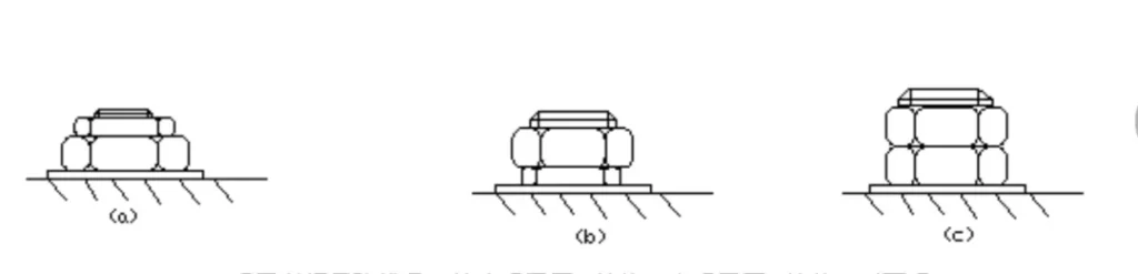
A double-helix anti-loosening method is adopted. The structure shown in Figure (a) is prohibited. The structure shown in Figure (b) should be used, with a flat nut at the bottom and a thick nut at the top. However, considering that the wrench cannot enter the bottom to tighten the flat nut, the structure with two thick nuts can only be used, as shown in Figure (c).
2. The two locating pins should be of different lengths
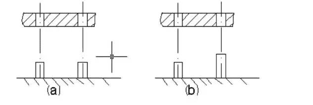
The assembly of large boxes often requires the use of several locating pins. It is not advisable to make all the locating pins the same height, as shown in Figure a, because it is difficult to align several locating pins at the same time when closing the box. The locating pins should be made of different lengths, as shown in Figure b. When closing the box, it is easier to align one locating pin first.
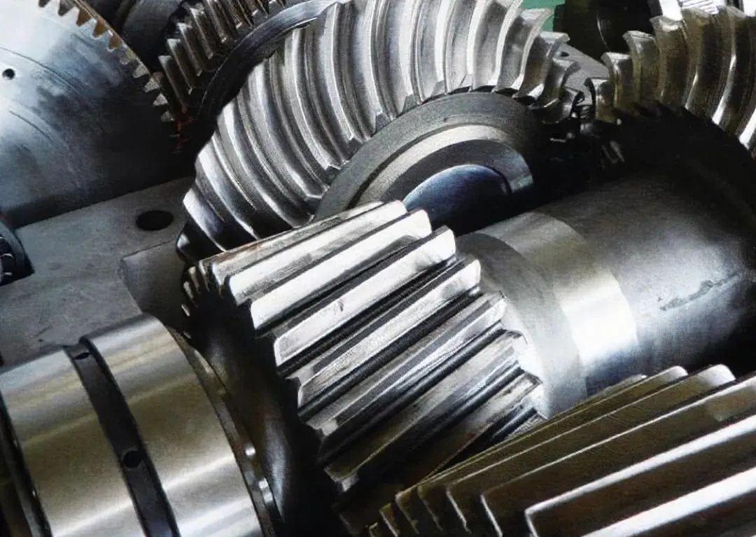
3. The correct configuration of the large and small gears in gear transmission
To facilitate installation and prevent stepped wear during gear operation, the pinion should generally be 5-10 mm wider than the gear, as shown in Figure c. However, if the pinion is made of plastic, its tooth width should be smaller than that of the gear, as shown in Figure d, to avoid dents being worn into the gear.
4. Screw connections that are frequently disassembled and reassembled.
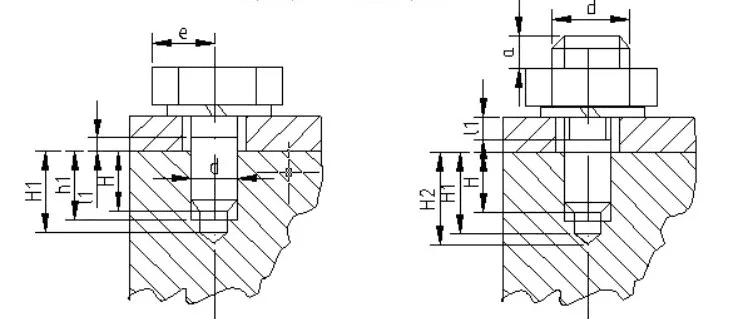
As shown in Figure a, the screw connection is characterized by the screw being directly screwed into the threaded hole to be connected, without the need for a nut. The structure is relatively simple and compact, suitable for applications where bolt connections are not feasible. Screw connections are not suitable for applications involving high stress or frequent disassembly and assembly. Frequent disassembly and assembly can easily cause thread wear, potentially leading to the failure of the connected parts. If frequent disassembly and assembly are required, a double-ended bolt connection can be used, as shown in Figure b. The screwing depth is H. When the screw hole is made of steel or cast iron, H≈d, when the screw hole is made of cast iron, H=(1.25~1.5)d, when the screw hole is made of aluminum alloy, H=(1.5~2.5)d. The threaded hole depth H1=H+(2~2.5)p (p is the thread pitch), and the drilling depth H2=H1+(0.5~1)d.
5. Intermediate bearing assembly for high-speed shafts
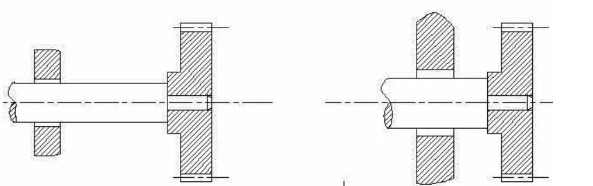
When installing a coupling on a rotating shaft end, the structure shown in Figure a is prohibited. The cantilever length should be minimized. The larger the cantilever, the greater the deformation and unbalanced weight. Therefore, when installing a coupling on the cantilever end, in addition to minimizing the weight of the coupling, it should also be placed as close as possible to the bearing.
6. Machining of small-diameter deep holes
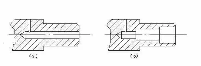
Machining small-diameter deep holes is difficult, costly, and inefficient. It is prohibited to design deep, small-diameter lubrication holes on rotating shafts, as shown in Figure a. Under the condition that it is possible, the holes should be made as large as possible. If necessary, they should be made into different diameters as shown in Figure b.