Titanium alloys may be strong, but machining them is tough, especially thin-walled parts. Cutting operations often cause stress-induced deformation and dimensional inaccuracies, leaving many frustrated! Don’t panic, a comprehensive solution can fix it: Adjust wire cutting and CNC milling paths, optimize machining strategies, then enhance part rigidity with positioning fixtures and enclosed cutting methods. This minimizes deformation at its source, ensuring consistent product quality.
1. Preface
Titanium alloy materials possess high strength, excellent corrosion resistance, superior heat resistance, and considerable hardness, making them widely used in aerospace applications. Their drawbacks include poor thermal conductivity and challenging machinability.
The titanium alloy spacer part measures 43mm in length, 25mm in width, and 3.5mm in thickness. The thickness and the two central internal cavities are formed via CNC milling, while the eight external ribs are produced by wire cutting. This ensures a rib width of (0.3±0.05)mm and a symmetry tolerance of 0.05mm relative to the internal cavities, classifying it as a fine-rib component. During the initial production run of 10 parts according to the process documentation, inspection revealed that 4 parts exhibited dimensional deviations in rib width and symmetry, failing to meet design requirements.
2. Cause Analysis
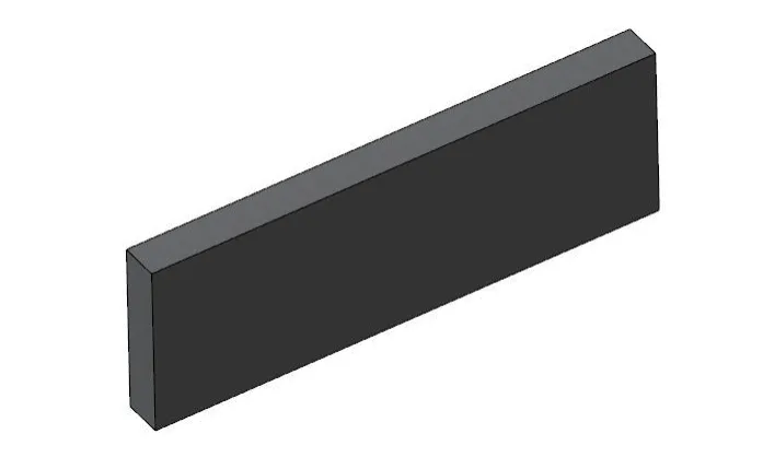
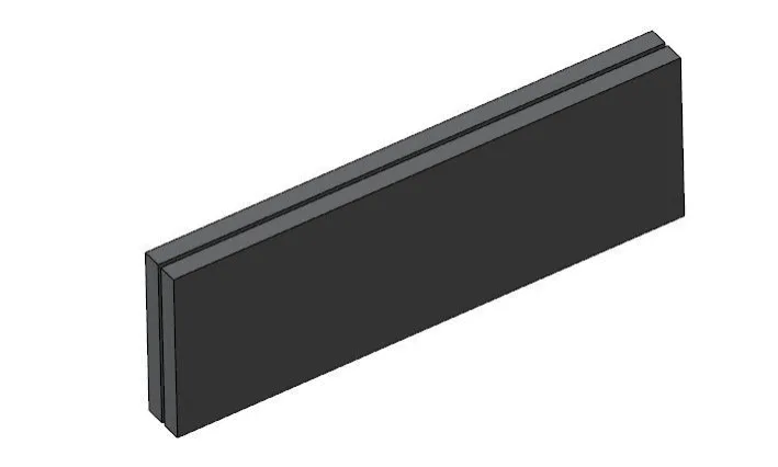
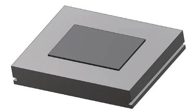
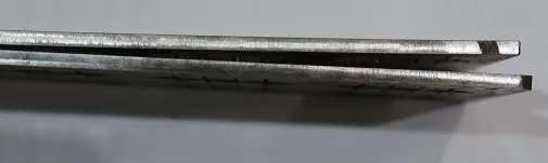
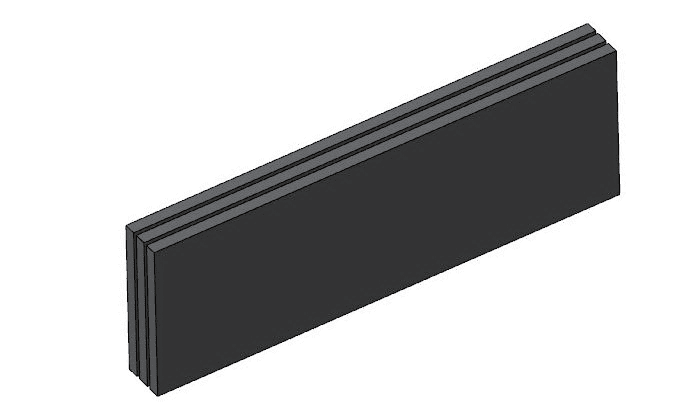
The original process documentation specified a raw material thickness of 5mm for the part. Due to inventory model limitations at the facility, only 18mm thick raw material was available. Therefore, the blank cutting dimensions were set to 250mm × 80mm with a thickness of 18mm, as shown in Figure 1. An additional wire-cutting process was incorporated to halve the material thickness (see Figure 2), resulting in 9mm-thick sections. These sections were then CNC-milled to a final thickness of 3.5mm. During CNC milling, the operator employs a vacuum chuck clamping method (see Figure 3). First, one surface is precision-milled to remove a 3mm allowance. After flipping the part and re-securing it with the vacuum chuck, the second surface is milled to a thickness of 3.5mm. Finally, the internal cavity in the center of the part is machined.
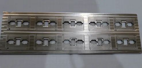
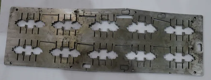
Arrange 10 small parts on each material sheet (see Figure 4). Drill a 3mm center hole at one end of each row of parts for wire threading, then proceed to the wire cutting process to machine the part outlines.
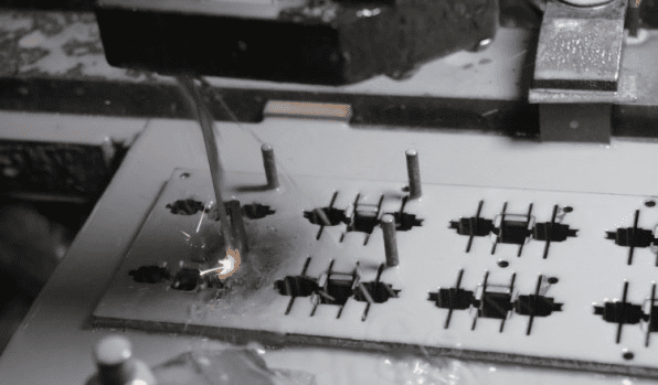
Before processing, wire cutting operators inspected the material’s flatness and discovered stress-induced deformation (see Figure 5), with the maximum deformation amounting to 3.05mm. Cutting was performed using a clamping plate. Since only one wire feed hole was available, each small part became interconnected after cutting, and the material was severed. Consequently, under stress, material deformation occurred during processing (see Figure 6), causing the rib width dimensions to exceed tolerances and thereby affecting symmetry with the inner cavity.
3. Implement Effective Measures
Analysis revealed that the primary issue lies in material stress deformation. During machining, titanium alloy generates cutting heat and dissipates it slowly. The greater the material removal, the larger the resulting deformation. This can only be addressed by modifying the cutting method. The original machining plan was optimized by implementing the following effective measures:
1) Replace high stress with low stress. During CNC milling, larger cutting allowances generate greater stress, leading to increased material deformation. The wire-cutting process for raw materials was modified from splitting into two pieces to splitting into three pieces (see Figure 7). This resulted in each material piece being approximately 6 mm thick, significantly reducing the CNC milling allowance and thereby minimizing material deformation.
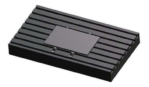
2) Modify the CNC milling clamping method. When machining thicknesses via CNC milling, switch from vacuum suction cup clamping to side-top clamping (see Figure 8). By repeatedly flipping the part to precision-mill both sides with a cutting depth ≤0.2mm per pass, the thickness is ensured to meet drawing specifications while minimizing material deformation. Calculations indicate that post-CNC milling, controlling overall material deformation within 0.5mm satisfies the flatness requirements for individual small components. Operators follow the optimized method, performing in-process inspection to ensure flatness ≤0.2mm.
3) Fabricate specialized tooling to increase the number of threading holes. For the wire cutting process, to prevent material deformation during machining, the number of threading holes was increased to 10. This ensures each spacer part has an independent threading hole, formed in a single CNC milling operation to guarantee consistency. A wire cutting fixture was fabricated, securing the workpiece to the fixture plate via locating pins (see Figure 9). Each spacer is machined independently without cutting through adjacent parts, enhancing material rigidity and minimizing part deformation.
4. Effect Verification
Twenty parts were trial-machined according to the improved plan. Professional inspection equipment confirmed that all rib width dimensions and symmetry met drawing requirements. Ultimately, 120 parts were processed in this batch, all meeting specifications with a 100% pass rate, demonstrating the effectiveness of the improvement plan.
5. Conclusion
This article presents a machining process and deformation control method for thin-sheet titanium alloy parts. By optimizing the machining plan and clamping method, modifying the wire-cutting path and CNC milling strategy, and employing positioning fixtures and enclosed cutting to reduce cutting stress deformation, the rib width dimensions and symmetry requirements were effectively ensured. This approach provides valuable experience for machining similar parts.


