1. What is Vibration?
Vibration is a mechanical phenomenon in which an object oscillates around a point of equilibrium. These oscillations may be periodic, like the swing of a pendulum or random, like the movement of a car tire on a gravel road.
Sometimes, vibration is desirable. For instance, the sound from a mobile phone is audible precisely because sound vibrates through the air. However, more often than not, vibration wastes energy while causing unwanted deformation and noise. For instance, most vibrations produced by engines, electric motors, and other operating machinery are undesirable. Issues like unbalanced rotating components, uneven friction, and gear meshing can trigger vibrations, which meticulous mechanical design typically strives to minimize.
2. Why Does Machining Produce Vibration?
Machine tools, workpieces, and cutting tools are not perfectly rigid. Cutting forces cause them to vibrate. The dynamic characteristics of these components limit cutting performance. Insufficient rigidity and inadequate vibration damping can lead to self-excited vibration or “chatter” issues. With a fundamental understanding of this phenomenon, chatter can be predicted, aiding in the improvement of cutting performance.
3. Why Should Vibration be Minimized During Machining?
Vibration during machining causes numerous negative effects, the most significant of which include:
- Excessive cutting edge wear and the occurrence of uncontrolled, unpredictable wear patterns (e.g., chipping and cracking of cutting edges), compromising machining reliability.
- Reduced surface finish on workpieces, potentially leading to scrap or rework. This may cause issues with delivery times and reliability.
- As mentioned above, vibration impacts the economics of our machining operations, resulting in additional financial waste.
- Since vibration requires energy, it also wastes resources and poses challenges to the professional competence of machining operators.
4. What are the Different Types of Vibration in Machining?
Free Vibration in Cutting
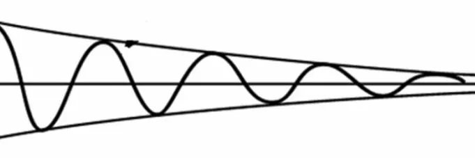
Free vibration occurs when an initial input triggers vibration in a mechanical system, causing the system to oscillate freely thereafter. This resembles what happens when you pull a child’s swing back and then release it. The mechanical system then oscillates at one or more of its “natural frequencies” before gradually damping to zero.
5. Forced Vibration in Machining
Forced vibration occurs when a mechanical system is subjected to a time-varying disturbance (load, displacement, or velocity). The disturbance can be periodic, a steady-state input, or a random input. Examples include an unbalanced washing machine shaking or a building vibrating during an earthquake.
The system’s frequency response is one of the most critical characteristics of forced vibration. In a phenomenon called resonance, the vibration amplitude becomes extremely high when the forced frequency approaches the natural frequency of a lightly damped system. The system’s natural frequency is termed the resonance frequency. When pushing a child on a swing, force must be applied at precisely the right moment to make the swing go higher and higher. The push simply keeps adding energy to the system. In rotor-bearing systems, any rotational speed that can excite the resonance frequency is called a critical speed.
6. Resonance Vibration in Machining
Resonance in machining can lead to systematic failures. Therefore, vibration analysis must predict when such resonance might occur and determine preventive measures. Adding damping can significantly reduce vibration amplitude, while altering the system’s stiffness or mass can shift the natural frequency away from the forced frequency. If the system itself cannot be modified, perhaps the frequency can be changed (e.g., by adjusting the machine tool’s speed).
7. Influence of Cutting Forces on Vibration Phenomena
The forces acting on the metal being cut also exert themselves on the cutting tool. These forces cause the cutting tool to deform and bend, potentially leading to vibration.
The dynamic nature of cutting forces can induce resonant vibration. The risk increases when using slender cutting tools or workpieces, excessive cutting forces, materials lacking damping properties, incorrect cutting methods, or improper tool geometry.
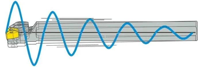
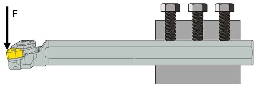
Figure 6 shows a steel tool holder (100 mm diameter, 500 mm overhang).
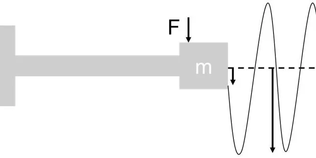
At a static cutting force of 500 N, this tool exhibits 25 μm of deflection. If the cutting force varies sinusoidally at 142 Hz, variable deflection occurs with an amplitude 20 times greater than the static deflection. This leads to resonant vibration.
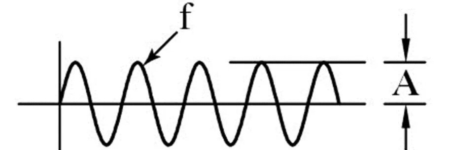
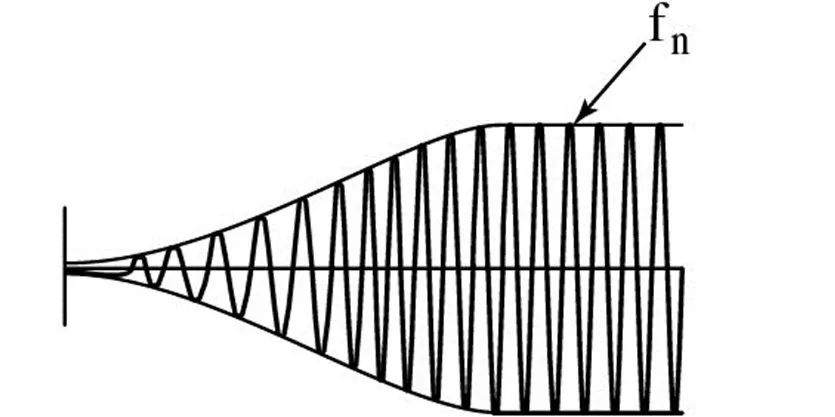
Resonant vibration occurs when the frequency at which the cutting force acts on the cutting edge equals the tool’s natural frequency (resonance frequency). This can be triggered by variations in cutting conditions (during milling), intense intermittent interrupted cutting, or even irregularities in the material structure (see Figure 7).
Machinists also refer to resonant vibration as chatter. Chatter itself is not inherently a major problem, but in certain situations, it can compromise machining quality due to uncontrolled wear on the cutting edge or poor surface finish on the workpiece. In such cases, chatter suppression is necessary. This is most easily achieved by altering cutting conditions, followed by modifying tool selection.
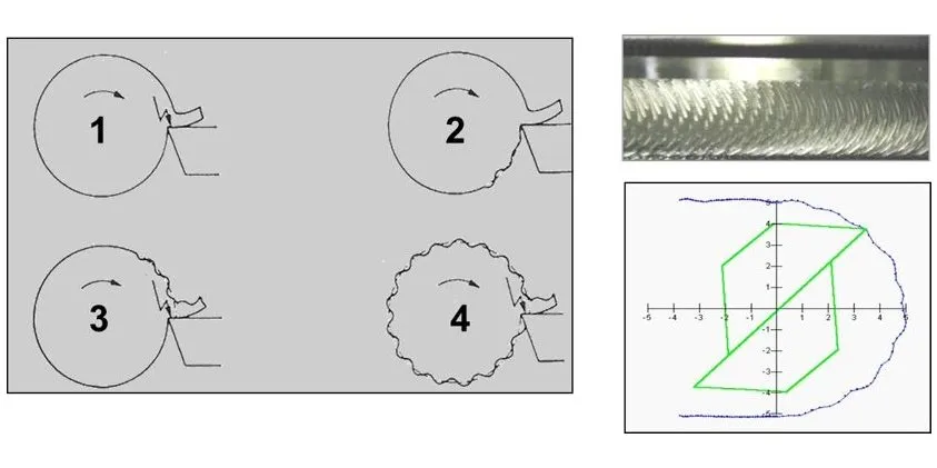
In the example above, Stage 1 represents a situation where material irregularities introduce dynamic components into the cutting forces. In Stage 2, irregularities in the workpiece material cause variations in chip thickness. This results in sustained dynamic cutting forces that, when their frequency approaches the tool’s natural frequency, generate resonant vibration.
8. The Impact of Machine Tool Stability on Vibration
Any analysis of vibration and its risks during machining processes must consider machine tool stability. Machine tools cannot provide infinite stability, and generally, tool stability decreases as the machine tool spindle speed increases (see Figure 8).
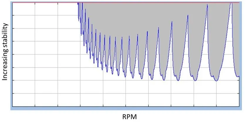
Generally, the higher the revolutions per minute (rpm) during machine tool operation, the greater the risk of vibration. However, stability may improve at specific rotational speeds. The selected rpm for a particular cutting tool may fall within a range of poor stability, triggering vibration that necessitates reducing the machine speed to eliminate it. Conversely, the chosen rpm may reside in a zone of high stability, allowing cutting conditions to be maintained at higher levels. To avoid vibration, especially during high-speed machining, select the rotational speed with caution.
9. How is the Deflection of a Single-ended Clamped Cylindrical Beam Determined?
In general mechanics, the model shown in the figure below (Figure 9) can be used to determine the deflection of a single-ended clamped cylindrical beam (e.g., an internal turning tool holder, milling cutter, drill bit, etc.). Simply put, greater deflection increases the risk of harmful vibrations (including resonance), while reducing tool deflection lowers this risk.
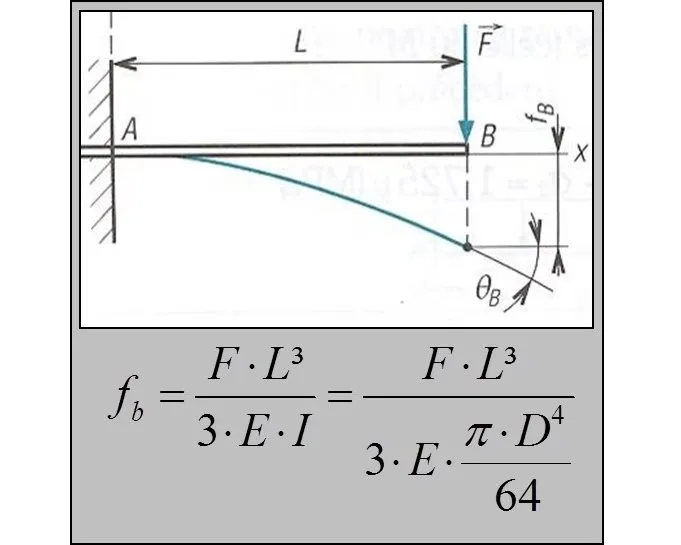
From this perspective, minimizing tool deformation or deflection is essential to reduce vibration risk.
This can be achieved through several methods:
• Reducing cutting forces or altering the direction in which cutting forces act on the system.
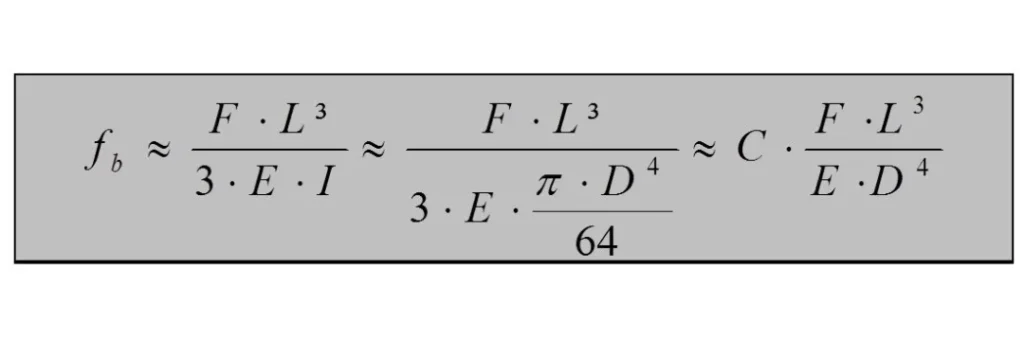
• Enhancing tool strength to provide greater resistance to bending. The formula in Figure 10 indicates that doubling the overhang length increases deflection by a factor of 8, while doubling the diameter reduces deflection by a factor of 16. Therefore, shorter tools or larger-diameter tools carry a lower risk of vibration. Consequently, the overhang ratio (L/D, where unsupported length or overhang is divided by diameter) is often used as a quick metric for assessing vibration risk.
Some reference guidelines based on the overhang ratio are as follows:
If the overhang ratio is less than 3, vibration typically does not occur.
If the overhang ratio is less than 6, there is a risk of vibration.
If the L/D ratio is less than 9, vibration may occur.
If the L/D ratio exceeds 9, vibration will definitely occur, and conventional tools often fail to resolve the issue.
• Use tool materials with higher stiffness. The modulus of elasticity (E) is a key factor. For example, replacing steel tool holders with carbide holders can reduce deflection by up to 50%. This approach can be combined with the use of tapered tools.
10. Overhang Considerations in Vibration
Exercise caution when using the overhang ratio to predict vibration risk. Further analysis of the formula in Figure 9 yields the equation shown in Figure 10. Presented and applied to two examples, this formula provides valuable insight. First, a tool with a 200mm overhang and 50mm diameter has an overhang ratio of 4. Second, another tool with a length of 100 mm and a diameter of 25 mm also has an overhang ratio of 4. Do these two tools exhibit the same vibration risk? Substituting their respective values into the formula in Figure 10 reveals that the second tool’s deflection is twice that of the first, meaning its vibration risk is also twice as high.
When vibration risk is high, tool diameter is the most critical factor.
11. How can Vibration During Machining be Minimized and Controlled?
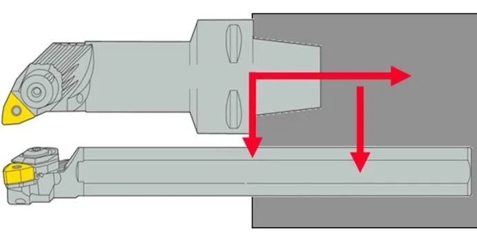
Several practical steps can minimize or eliminate vibration risk. Apply all these steps to alter the magnitude or direction of cutting forces acting on the tool.
o Use a cutting edge angle close to 90°.
o Employ a smaller tip radius and/or sharper cutting edges.
o Reduce cutting depth and increase feed rate.
o Adjust cutting speed.
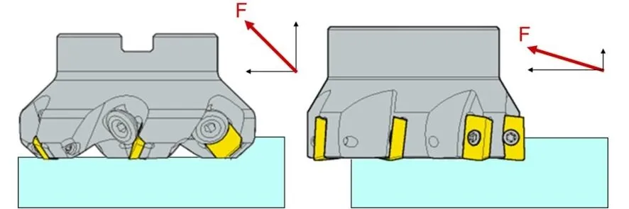
In milling applications, the first recommendation—“Use a cutting edge angle close to 90°”—is applied differently. As in turning, the resulting cutting forces will be roughly perpendicular to the cutting edge (see Figure 12). When evaluating the bending risk of a milling cutter mounted in a milling machine spindle (see Figure 13), assess vibration risk by multiplying the cutting force by the distance between the cutting force direction and a “reference” point within the spindle. Every machine tool spindle contains a fixed reference point around which the spindle can oscillate.
When comparing a square shoulder milling cutter with a 90° rake angle to a high-feed milling cutter with only a few degrees of rake angle (Figure 13), the former exhibits a smaller distance between the cutting force direction and the reference point. Consequently, under identical cutting forces, it carries a lower vibration risk.

12. Checklist for Reducing Vibration Based on Your Operating Conditions
How to reduce vibration during milling?
To address vibration in milling, select appropriate tools and cutting conditions to alter the magnitude and direction of cutting forces.
- Select milling cutters with coarse tooth pitch and mount them with the smallest possible overhang length.
- Choose cutting edges with positive rake angle geometry.
- Select milling cutters with smaller diameters.
- Choose smaller cutting edge radii.
- Select carbide grades with thinner coatings.
- Employ larger feed per tooth. Reduce spindle speed while maintaining table feed rate to achieve greater feed per tooth. Do not decrease feed per tooth when vibration occurs.
- Reduce axial and radial cutting depth.
- Use a stable cutter clamping system. For modular toolholding systems, employ the largest possible connection size. Utilize tapered toolholding.
- Position the cutter centrally on the workpiece. Employ climb milling.
Start with normal feed rates and cutting speeds. If vibration occurs, adjust incrementally as follows:
1. Increase feed rate.
2. Raise spindle speed.
3. Lower spindle speed.
4. Decrease feed rate until vibration ceases or is minimized.
How to reduce vibration during turning?
The following steps influence turning results. Use them as a checklist for troubleshooting vibration issues.
- Select a basic tooling system and dimensions that maximize stability and rigidity. Mount the tool with the shortest possible overhang length. This increases the tool’s natural frequency and reduces deflection, making it easier to avoid vibration and suppress it if it occurs.
- Carefully select insert type, size, and corner radius. Use the smallest possible corner radius, ideally less than the cutting depth, to minimize passive cutting forces. Limit cutting depth to minimize tool deflection and ensure accurate workpiece tolerances. When vibration is likely, select inserts with smaller top angles (60° or 55°) to achieve smooth cutting while maintaining adequate edge strength.
- Choose inserts with sharp edges and well-defined cutting edge geometry for effortless cutting and reduced tool deflection. Note that sharper cutting edges are weaker and require appropriate chip breaking.
- Select inserts with tougher carbide grades and sharper geometries, though this reduces cutting edge strength and may lead to premature chipping or breakage. To enhance cutting edge reliability and tool life, compensate for the reduced geometric strength by using tougher cutting materials.
- Carefully select cutting conditions to minimize cutting depth. When severe vibration risks exist, use feed rates at least 25% greater than the tool tip radius. Evaluate cutting speeds to avoid machining within RPM ranges where machine stability is poor.
How to Reduce Vibration During Boring Operations?
The following steps can influence boring results. Use them as a checklist for troubleshooting vibration issues.
- Check the overhang ratio and adjust the tool if necessary. Can a larger diameter tool be used? Can a tapered tool type be employed? Can a modular tool type with different diameters be selected?
- Optimize tool clamping as much as possible.
- Position the cutting edge at the center height.
- Select cutting edges with positive geometry and smaller radii. Choose carbide grades with thinner coatings.
- Carefully select insert type, size, and tip radius. Select the smallest possible tip radius, ideally less than the cutting depth, to minimize passive cutting forces. Limit cutting depth to minimize tool deflection and ensure accurate machining tolerances. When vibration is likely, choose inserts with smaller rake angles (60° or 55°) to achieve smooth cutting while maintaining good edge strength.
- Select inserts with sharp edges and well-defined cutting edge geometry to achieve smooth cutting with minimal tool deflection. Note that sharper cutting edges are weaker and require appropriate chip breaking.
- Select carbide grades with higher toughness and sharper geometries, though this reduces cutting edge strength and may lead to premature chipping or breakage. To enhance cutting edge reliability and tool life, compensate for the reduced geometric strength by using tougher cutting materials.
- Carefully select cutting conditions to minimize cutting depth. When severe vibration is a risk, use a feed rate at least 25% greater than the tool tip radius. Evaluate cutting speeds to avoid machining within RPM ranges where machine stability is poor.


