1. Project Background
In the world of industrial printing technology, precision is the difference between a high-fidelity output and a mechanical failure. The component in this study is a Datum Block. This part serves as a foundational alignment component within a high-speed printer’s assembly, where it must facilitate perfect synchronization between various moving mechanical arms and the printing substrate
For the OEM, the challenge was finding a precision machining partner capable of holding extremely tight tolerances on aluminum—a material known for its thermal sensitivity—while adhering to the strict ISO 2768-1-f (Fine) general tolerance standard.
2. Part Introduction
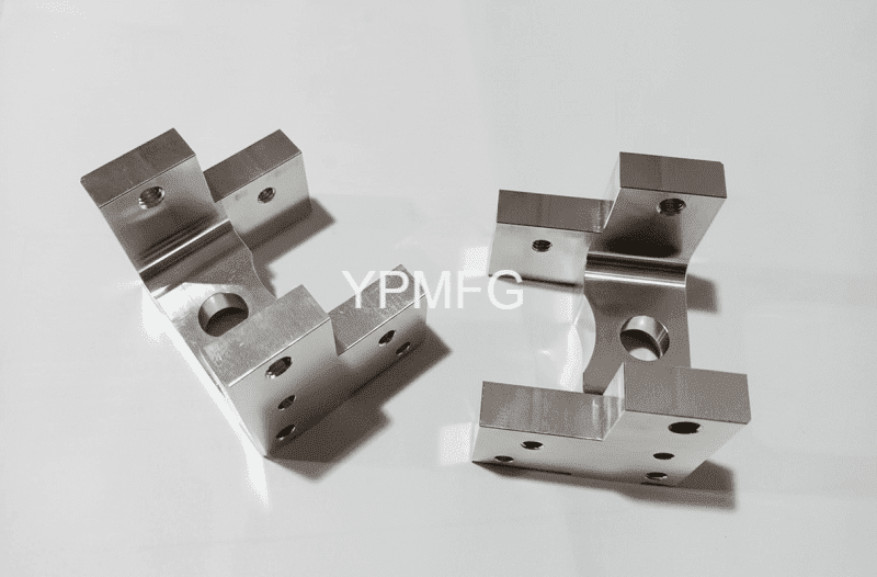
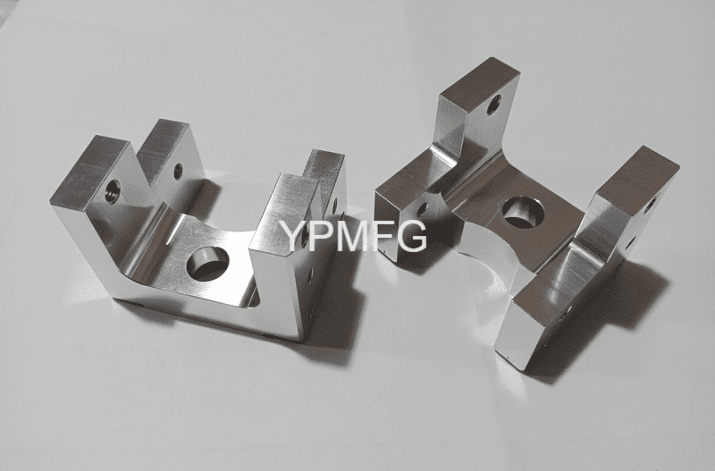
The Datum Block is a compact yet geometrically dense component designed for high-load, high-repetition environments.
- Part Name: Datum Block.
- Material: 5000 or 6000 Series Aluminum (chosen for its excellent strength-to-weight ratio and machinability).
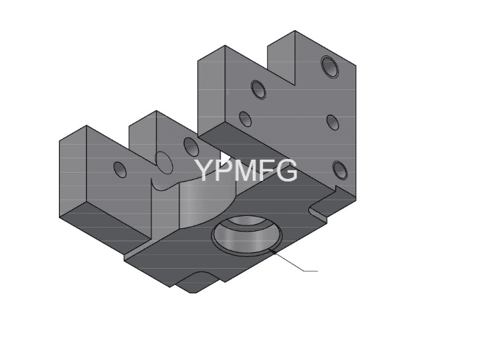
- Key Geometric Features:
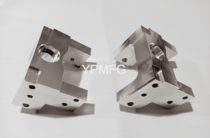
- Primary Functional Bore: A 16.01 ± 0.01 mm precision hole.
- Depth-Specific Tolerance: A unique requirement where the ±0.01 mm tolerance applies strictly up to a depth of 3 mm.
- Positioning Holes: Two 4 H7 precision holes for dowel pin alignment.
- Threaded Interfaces: Multiple M5-6H and M6-6H threaded holes for component mounting.
- Through-hole: A Φ 11 “thru all” hole for structural clearance.
- Critical Surfaces: Datums A, B, and C used to establish a 3D coordinate system for all subsequent features.
3. Precision Machining Challenge Analysis
As an experienced CNC machining provider, our engineering team identified three primary technical hurdles in the drawing:
A. The ± 0.01 mm Tolerance Barrier
Machining a 16.01 mm bore with a total tolerance band of only 20 microns (0.02 mm) is challenging in aluminum. Aluminum has a high coefficient of thermal expansion, a slight temperature fluctuation in the workshop or heat generated during the cut can cause the part to expand beyond the tolerance limit.
B. The 3mm Depth Constraint
The drawing specifies: “Tolerance only applies up to 3mm deep”. This indicates that the entry point of the bore is the most critical functional area. From a machining perspective, this requires a tool entry strategy that avoids “bell-mouthing” (where the hole is wider at the top) and ensures the transition from the precision zone to the standard zone is seamless.
C. Complex Geometrical Relationships
The part features several position tolerances of 0.1 relative to Datums A and C. Furthermore, there is a flatness requirement of 0.05 on the secondary datum surface B. Maintaining these relationships requires a highly stable workholding strategy to prevent part deflection during high-speed milling.
4. Manufacturing Solution & Process
To produce these custom machined parts with 100% repeatability, we implemented a robust CNC workflow.
Step 1: Material Preparation and Stress Relieving
We utilized 6061-T6 aluminum billet. Before the final precision passes, the parts underwent a stress-relieving cycle to ensure that once the material was removed, the internal stresses would not cause the $0.05$ flatness or the 16.01 mm bore to warp out of spec.
Step 2: High-Speed CNC Milling (Roughing)
Using a 4-axis CNC machining center, we performed the bulk material removal. We utilized high-efficiency milling (HEM) paths to minimize heat transfer into the part. All threaded holes, including the M5 and M6 features, were pre-drilled at this stage.
Step 3: Precision Boring and Reaming
The 16.01 ± 0.01 mm bore was the critical path.
- Boring: We used a micro-adjustable fine boring head. This allowed our operators to compensate for tool wear in increments of 0.002 mm.
- Reaming: The 4 H7 holes were finished using carbide reamers to ensure a mirrored surface finish and perfect cylindricality.
Step 4: Finishing and Deburring
Per the technical requirements, all edges received a 0.6 * 0.6 mm approx chamfer. We used a specialized 45-degree chamfer mill to ensure the “approx” requirement was met with visual and tactile consistency across the batch.
Step 5: Quality Control (QC)
- CMM Verification: We used a Coordinate Measuring Machine (CMM) to verify the 0.1 position tolerances relative to the ABC datum structure.
- Air Gauging: For the 16.01 ± 0.01 mm bore, air gauging was used to provide a non-contact, high-precision measurement of the first 3 mm of depth, ensuring compliance with the specific depth note.
5. Results and Value for the Customer
Our specialized approach to this printer equipment component resulted in several key benefits for the client:
- 100% Dimensional Compliance: Every part in the batch met the 16.01 ± 0.01 mm requirement, significantly reducing the client’s incoming inspection rejection rate.
- Optimized Assembly Time: Because we held the 4 H7 holes to the tight end of the specification, the client reported that dowel pins pressed in with perfect resistance, speeding up their final assembly line.
- Superior Surface Integrity: By following the ISO 2768-1-f “Fine” standard, we provided a finish that met the high aesthetic and functional standards of high-end office equipment.
- Cost-Effective Scalability: Our use of 4-axis machining allowed us to finish the part in fewer setups, reducing the unit cost for the customer compared to traditional 3-axis methods.
6. Conclusion
The manufacturing of the Datum Block demonstrates that precision machining is not just about having the right machines, it’s about the engineering insight to interpret complex technical notes like the “3mm deep” tolerance constraint.
Whether you are in the printing, medical, or aerospace industry, your project deserves this level of attention to detail. At YPMFG, we specialize in turning complex CAD files into high-performance reality.
Looking for a reliable partner for your next CNC machining project? Contact us today for a DFM (Design for Manufacturing) review and a competitive quote.
