Table of Contents
Crystal Structure of Metals
Crystals and Amorphous Crystals
Matter is composed of atoms. Depending on how these atoms are arranged within the material, it can be divided into two main categories: crystals and amorphous materials.
Crystals: Atoms are arranged in a regular pattern. All solid metals are crystals.
Amorphous crystals: Atoms are arranged irregularly. Examples include glass, rosin, and asphalt.
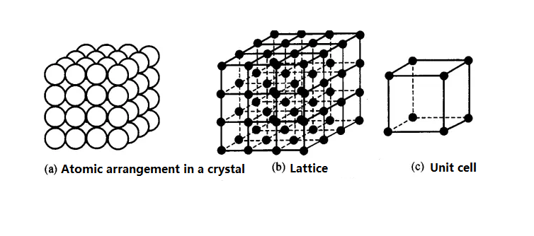
The various regular arrangements of atoms within a crystal observed with an electron microscope are called the crystal structure of a metal. The arrangement of atoms within a crystal is called the crystalline structure.
Metal atoms are held together by the interaction between positive ions and free electrons, known as metallic bonds.
Lattice and Unit Cell
Lattice: A three-dimensional grid formed by connecting the centers of atoms with imaginary straight lines. The intersections of these lines (atomic centers) are called nodes.
Unit Cell: The smallest geometric unit that fully reflects the characteristics of a crystal lattice.
Crystal Structures of Common Pure Metals
Common crystal structures of pure metals include body-centered cubic lattice, face-centered cubic lattice, and close-packed hexagonal lattice.
Body Centered Cubic Lattice(BCC)
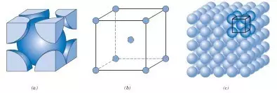
The number of atoms in a body-centered cubic unit cell is 1/8 x 8 + 1 = 2, and the density is 0.68.
Body-centered cubic: Cr (chromium), W (tungsten), V (vanadium), Cb (niobium), Ta (tantalum), Mo (molybdenum), and steel (α-Fe, δ-Fe).
Face Centered Cubic Lattice(FCC)

The number of atoms in a face-centered cubic unit cell is 1/8×8 + 1/2×6 = 4, and the density is 0.74.
Face-centered cubic: Al (aluminum), Cu (copper), Au (gold), Pb (lead), Ni (nickel), Pt (platinum), Ag (silver), and steel (γ-Fe).
Hexagonal Close Packed Lattice (HCP)
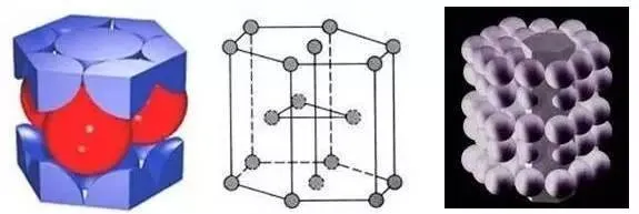
The number of atoms in a close-packed hexagonal unit cell is 1/6×12 + 1/2×2 + 3 = 6, with a density of 0.74.
Hexagonal close-packed: Zn, Mg, Zr, Ca, Co, Mn, Ti.
Impact toughness and polycrystals
Impact toughness refers to the property of the amount of energy consumed when a material breaks under an external impact load.
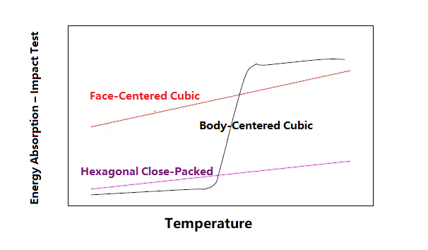
The impact toughness of a body-centered cubic lattice decreases dramatically, and a brittle-ductile transition temperature is reached.
Metals in practical use are composed of many grains, also known as polycrystals. Each grain is equivalent to a single crystal. The atomic arrangement within the grain is identical, but the orientation of the atoms in different grains varies. The interfaces between grains are called grain boundaries.
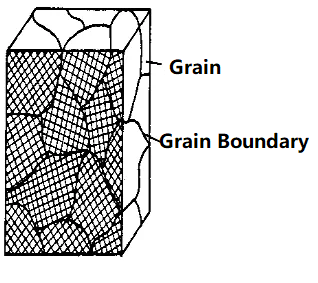
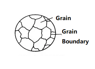

The process of cooling high-temperature liquid metal into solid metal is a crystallization process, where atoms transition from an irregular (liquid) state to a regular (solid) state. The crystallization process always begins with a nucleus, typically formed by solid impurities in the liquid metal. Atoms in the liquid continuously gather toward the nucleus, causing it to grow. Simultaneously, new grains are generated in the liquid and continue to grow until all the grains grow to contact each other, marking the end of crystallization.
Crystallization process and crystal defects
The atomic arrangement of actual crystals is not perfect. Due to various reasons, the atomic arrangement in many parts of the crystal is destroyed, resulting in various defects.
Common defects include:
① Point defects—vacancies, interstitial atoms, and substitutional atoms;
② Dislocations.
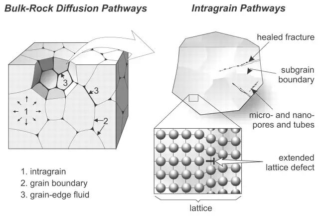
Point defects (vacancies, interstitial atoms, substitutional atoms) disrupt the atomic equilibrium and cause the surrounding lattice to bend, which is called lattice distortion. As a result, the metal’s yield point and tensile strength increase, while its plasticity and toughness decrease.

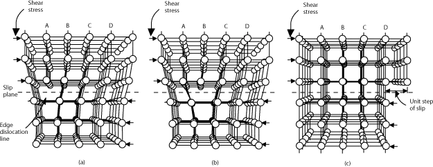
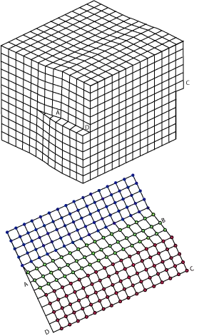
Dislocations occur when one part of a crystal lattice slips relative to another. The boundary between the slip and non-slip regions on the slip plane is called a dislocation. The presence of dislocations makes metals susceptible to plastic deformation and reduces their strength.
Iron-carbon alloy
Steel and cast iron are usually collectively referred to as iron-carbon alloys. Iron-carbon alloys are alloys composed of more than 95% iron, 0.05% to 4% carbon, and about 1% impurity elements.
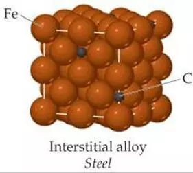
When the carbon content is less than 0.02%, it’s called pure iron (industrial pure iron).
Iron with a carbon content of 0.02% to 2% is generally called steel.
Iron with a carbon content greater than 2% is called cast iron.
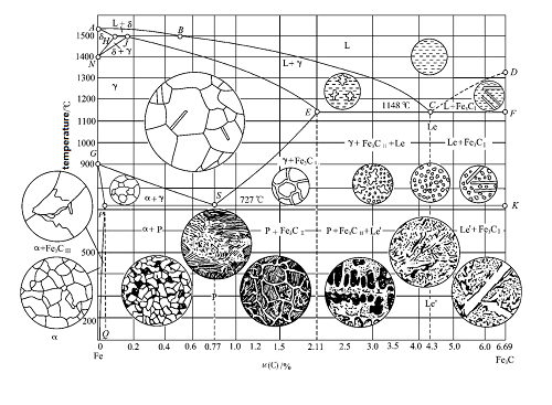
What is an alloy phase diagram?
The iron-carbon alloy phase diagram, also known as the iron-carbon phase diagram or iron-carbon alloy equilibrium diagram, is an experimentally constructed diagram that depicts the microstructure, properties, and interrelationships of iron-carbon alloys at different compositions and temperatures.
What do the horizontal and vertical axes represent?
The horizontal axis represents the percentage of carbon (0-6.69%), and the vertical axis represents the temperature. Multiple dividing lines divide the phase diagram into regions, each corresponding to a specific microstructure.What are the key points and lines in the iron-carbon alloy phase diagram? Point P: The boundary between pure iron and steel (0.0218% carbon content)
Point S: The eutectoid line (0.77% carbon content)
Point E: The boundary between steel and pig iron (2.11% carbon content)
Point C: The eutectic point (4.3% carbon content)
ACD: Liquidus, AECF: Solidus, GS: A3 line, ES: ACM line, ECF: Eutectic line (1148°C), PSK: Eutectoid line, also known as the A1 line (727°C).
Industrial pure iron (less than 0.0218% carbon content)
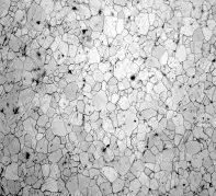
Microstructure: F+Fe3CⅢ, Ferrite (F) is a bright white matrix of pure iron with equiaxed crystals, primarily white. Ferrite has uniformly distributed grains (grade 6). The thin black stripes in the image represent grain boundary corrosion lines.
Basic structure of steel
The basic microstructures of steel are austenite, ferrite, and cementite (three types).
① Ferrite (F-ferrite)
A solid solution of carbon in α-Fe (below 910°C) is called ferrite, denoted by F or α.
A solid solution of carbon in δ-Fe (between 1390°C and 1535°C) is called δ-ferrite, denoted by δ.
Both α-Fe and δ-Fe have a body-centered cubic lattice (which is cold brittle). Ferrite has a very low carbon solubility, only 0.02% at 727°C and 0.0008% at room temperature, almost zero. Its metallographic structure consists of bright polygonal grains. It has high strength and hardness, good plasticity and toughness, and is ferromagnetic below 770°C, losing its ferromagnetism above 770°C. Grain size: Grain sizes range from 1 to 8. Grain size 8 is fine and uniform, with excellent overall mechanical properties.
② Austenite (A-austenite)
A solid solution formed by carbon dissolving in γ-iron (910°C-1390°C). γ-iron has a face-centered cubic lattice. It is represented by A.
Austenite has a greater carbon solubility than ferrite, reaching 2.11% at 1148°C and 0.77% at 727°C. Compared to ferrite, austenite has higher plasticity and lower hardness and yield point. In iron-carbon alloys, it exists only in the high-temperature range above 727°C and is not ferromagnetic. Therefore, it is often heated to the austenitic state during rolling and forging to improve its plasticity. Austenite has irregular polyhedral grains with straighter grain boundaries than ferrite.
③ Cementite (Fe3C-cementite)
A metallic compound of iron and carbon with a complex lattice structure. Cementite has a melting temperature of 1600°C and a carbon content of 6.67%. Cementite is very hard and extremely brittle, while its plasticity and toughness are almost zero. Cementite is weakly magnetic at low temperatures, but loses its magnetism above 217°C.
When the carbon content of an iron-carbon alloy is less than 2%, the structure consists of cementite interspersed within ferrite, resulting in carbon steel. When the carbon content exceeds 2%, some of the carbon exists as graphite, resulting in cast iron. Its tensile strength and plasticity are lower than those of carbon steel. However, cast iron has some vibration-absorbing properties. Because carbon has a low solubility in α-Fe, at room temperature, most of the carbon exists as cementite (Fe₃C).
In addition to the single-phase structure consisting of austenite, ferrite, and cementite, the basic structure of steel also includes a multiphase structure consisting of two basic phases: pearlite and ledeburite.
④ Pearlite (P-pearlite)
Pearlite is a mechanical mixture of ferrite and cementite arranged in alternating lamellar layers. The lamellar spacing and lamellar thickness depend primarily on the degree of undercooling during austenite decomposition. Based on lamellar thickness, austenite is classified as coarse pearlite (P), troostite (S), and troostite (T).
Under slow cooling conditions, an iron-carbon alloy with a carbon content of 0.77% undergoes only eutectoid reaction, resulting in a structure composed entirely of pearlite, known as eutectoid steel.
Pearlite has properties intermediate between ferrite and cementite, with high strength and hardness, as well as good plasticity.
Iron-carbon alloys with a carbon content greater than 0.77% are called hypereutectoid steels, with a structure composed of P + Fe₃C.
Iron-carbon alloys with a carbon content less than 0.77% are called hypoeutectoid steels, with a structure composed of F + P.
⑤ Ledeburite (Ld-ledeburite)
Ledeburite is a mixture of austenite and cementite. Ledeburite is a high-temperature structure that exists above 1148°C and has a carbon content of 4.3%.
Leedburite is very hard, very brittle, and has very poor plasticity.
Low-carbon steel is a hypoeutectoid steel, and its normal structure is ferrite F + pearlite P. The lower the carbon content, the greater the ferrite F content in the structure, improving the material’s plasticity and toughness, but also decreasing its strength and hardness.
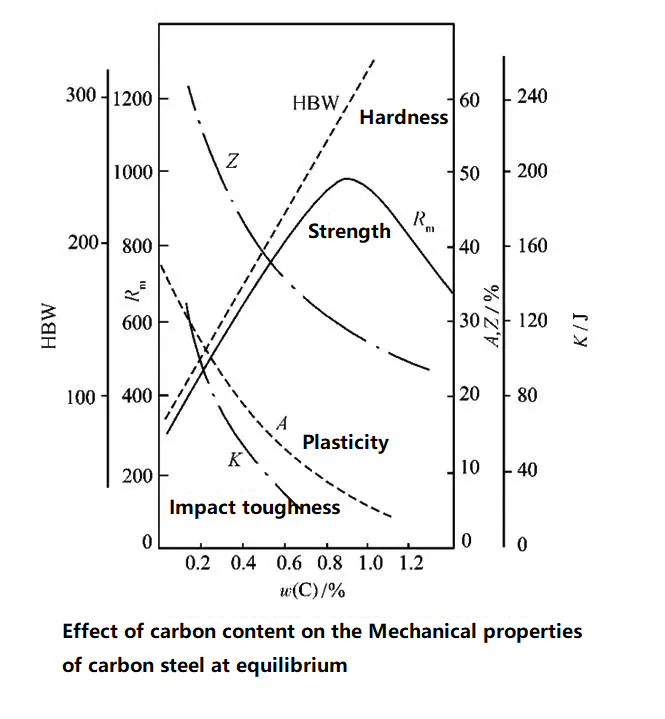
Effect of carbon content on performance
Strength: When C content is <0.9%, the strength of the steel increases with increasing C content. When C content is >0.9%, the strength of the steel decreases due to the network distribution of cementite at the grain boundaries.
Hardness: Increases with increasing C content.
Plasticity: Decreases rapidly with increasing C content.
Impact toughness: Decreases rapidly with increasing C content.
Heat Treatment Basics
Heat Treatment Knowledge
General Heat Treatment Process
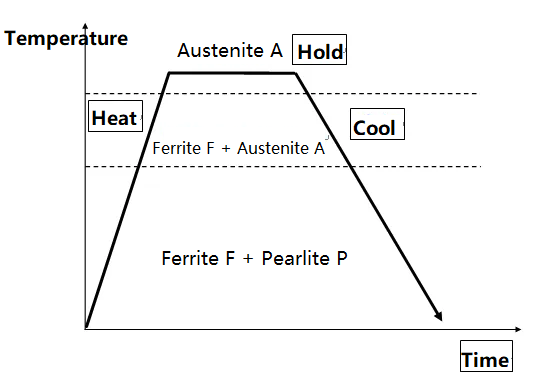
Heat treatment process: The heat treatment process primarily consists of three stages: heating, holding (for a certain period of time), and cooling. Temperature and time are the primary factors influencing heat treatment, and therefore, the heat treatment process can be described using a temperature-time curve.
Cooling steel is a key step in heat treatment. Steels of the same composition, after being heated to an austenitic structure, will exhibit different mechanical properties when cooled at different rates.

In actual production, cooling during heat treatment of steel always occurs at a certain rate, resulting in undercooling. The difference between the theoretical critical point and the actual critical point during cooling is the undercooling degree. For the same metal, the faster the cooling rate, the greater the compositional undercooling.
During heat treatment, steel undergoes structural changes during heating and cooling:
① Transformation during Heating—Austenite Formation:
At room temperature, the microstructure is F+P. When heated above Ac1, pearlite P transforms to austenite A. Continued heating causes the remaining ferrite F to dissolve into austenite A until the microstructure becomes a single austenite A.
② Transformation during Cooling—Decomposition of Austenite A:
The purpose of cooling is to decompose the high-temperature austenite A as the temperature decreases. During slow cooling, A transforms into F+P. However, actual cooling is not a slow process and involves a certain degree of undercooling. Therefore, the morphology, dispersion, and properties of the austenite decomposition products vary with cooling rates.
There are two cooling methods for studying the austenite transformation process: continuous cooling (close to reality) and isothermal cooling (austenite transformation is easy to measure).
a. Continuous Cooling:
This cooling process is closer to actual industrial production practices. It typically uses rapid cooling methods such as air or water cooling, as in normalizing and quenching.
In actual production, the transformation of supercooled austenite mostly occurs during a continuous cooling process. In this process, as long as the degree of supercooling corresponds to an isothermal transformation, the resulting microstructure and properties will also correspond.
b. Isothermal Cooling:
This cooling process, due to the holding period, occupies equipment and is time-consuming, making it unsuitable for continuous production. Therefore, it is often used for annealing at higher holding temperatures and for theoretical analysis of heat treatments.
A steel sample with a uniform austenite structure at a temperature above 727°C is rapidly cooled to a temperature below 727°C and then held at this temperature. After a period of time, the austenite begins to transform, and after a further period of time, the austenite transforms. The entire transformation process can range from a few seconds to several days. Plotting the start and end times of the austenite transformation at different temperatures yields the austenite isothermal transformation curve. Because the curve resembles the letter C, it is also called the C curve.
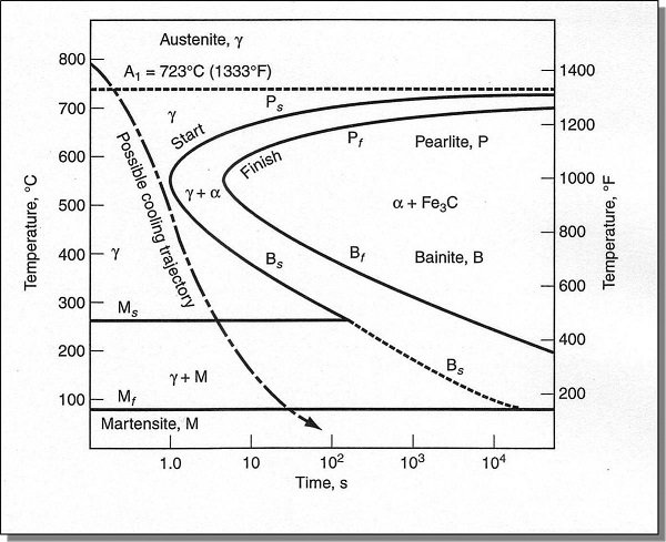
Notes: I: Pearlite (P) II: Western Pearlite (S) III: Extreme Western Pearlite (T) IV: Upper Bainite (B-upper) V: Lower Bainite (B-lower) VI: Martensite (M)
In actual production, it is almost impossible to obtain 100% of a single microstructure; a mixture of various microstructures is usually achieved.
What Factors Affect the C Curve?
The Effect of Carbon: Under normal heating conditions, the C curve of hypoeutectoid carbon steel shifts to the left with increasing carbon content (hypoeutectoid steel undergoes eutectoid decomposition during cooling of supercooled austenite, and ferrite begins to precipitate before the structure transforms into a pearlite-type structure). The C curve of hypereutectoid carbon steel shifts to the right with increasing carbon content.
The Effect of Alloying Elements: With the exception of cobalt, all alloying elements, when dissolved in austenite, increase its stability, causing the C curve to shift to the right. The shape of the C curve also changes when the content of carbide-forming elements is high.
Influence of heating temperature and holding time: With the increase of heating temperature and the extension of holding time, the composition of austenite becomes more uniform, the number of crystal nuclei for austenite transformation decreases, and the austenite grains grow and the grain boundary area decreases. These are not conducive to the transformation of supercooled austenite, improving the stability of supercooled austenite and causing the C curve to shift to the right.
Heat treatment process
Annealing
Annealing is a heat treatment process in which a steel specimen is heated to an appropriate temperature, held at that temperature for a specified period of time, and then slowly cooled to achieve a near-equilibrium microstructure. Depending on the material’s chemical composition and the purpose of the heat treatment, annealing can be categorized as full annealing, incomplete annealing, stress relief annealing, isothermal annealing, and spheroidizing annealing.
Full annealing, also known as recrystallization annealing, involves heating the workpiece to 30°C to 50°C above Ac3, holding the temperature, and then slowly cooling it in a furnace.
Its purpose is to homogenize the microstructure, eliminate stresses, reduce hardness, and improve machinability.
It is primarily used for castings and forgings of carbon and alloy steels within various hypoeutectoid steels, and is sometimes also used for welded structural components.
The fully annealed microstructure is close to the equilibrium microstructure (F+P) of the Fe-Fe3C phase diagram.
Incomplete annealing involves heating the workpiece to 30°C to 50°C above Ac1, holding the temperature, and then slowly cooling it.
Its primary purpose is to reduce hardness, improve machinability, and eliminate internal stresses.
Applicable to forgings and rolled products of low-alloy steels and medium- and high-carbon steels.
Stress relief annealing (PWHT) involves heating a workpiece to 100°C to 200°C below Ac1, holding the temperature, and then slowly cooling it to relax stresses caused by plastic deformation or creep deformation.
It aims to eliminate internal stresses generated by processes such as welding, cold forming, casting, and forging. It also allows for more complete diffusion of hydrogen within the weld, improving its crack resistance and toughness, and also improving the weld and heat-affected zone.
Normalizing
Normalizing is a heat treatment process in which a workpiece is heated to 30°C to 50°C above Ac3 or Acm, held for a specified period, and then cooled in air.
The objectives of normalizing and annealing are essentially the same: grain refinement, microstructure uniformity, and stress reduction.
Unlike annealing, normalizing involves a faster cooling rate and greater undercooling, which tends to increase the amount of pearlite in the microstructure and reduce the thickness of the pearlite lamellae. Therefore, normalized steel exhibits higher strength, hardness, and toughness than annealed steel.
Ultrasonic testing of some forgings with coarse grains can cause acoustic energy attenuation, which can be improved through normalizing.
Quenching
Quenching is the process of heating steel above its critical temperature (generally 30°C to 50°C above Ac3 for hypoeutectoid steels and 30°C to 50°C above Ac1 for hypereutectoid steels), holding the temperature appropriately, and then rapidly cooling it to transform austenite into martensite.
The goal is to obtain a martensitic structure through quenching, thereby increasing the material’s hardness and strength. This is beneficial for workpieces such as bearings and molds, but martensite is undesirable in the microstructure of boiler, pressure vessel, and weld materials.
Surface Hardening
Flame and induction surface hardening impart higher strength, hardness, and toughness to the surface layer of a part than to the core, while maintaining a certain degree of toughness in the core. Examples include bearing rollers and shafts.
Tempering
Tempering is a process in which quenched steel is heated to an appropriate temperature below Ac1, held for a specified period, and then cooled using a suitable method (usually air cooling) to achieve the desired microstructure and properties.
The purpose of tempering is to reduce internal stresses in the material and improve toughness. By adjusting the tempering temperature, varying degrees of strength, toughness, and hardness can be achieved to meet the required mechanical properties. Tempering also stabilizes workpiece dimensions and improves machining performance.
Low-temperature tempering at 150°C to 250°C produces tempered martensite with high hardness and wear resistance. It is primarily used for low-temperature tempering of high-carbon steel tools, gauges, ball bearings, and other materials.
Medium-temperature tempering at 300°C to 450°C produces tempered troostite with a certain degree of elasticity and toughness, as well as high hardness. It is primarily used for medium-temperature tempering of molds, springs, and other materials. High-temperature tempering at 500°C to 680°C. The resulting tempered bainite possesses a certain strength, high plasticity, and toughness. This heat treatment of quenching followed by high-temperature tempering is also known as “quenching and tempering.” Many mechanical parts, such as gears and crankshafts, require quenching and tempering. Some low-alloy, high-strength steel plates used in pressure-bearing special equipment also undergo quenching and tempering.
Solution Treatment and Stabilization of Austenitic Stainless Steel
Austenitic stainless steel is heated to 1050°C to 1100°C (at this temperature, carbon dissolves in austenite), held at this temperature for a specified period (approximately no less than 1 hour per 25mm of thickness), and then rapidly cooled to below 427°C (the cooling time from 925°C to 538°C should be less than 3 minutes) to achieve a uniform austenitic structure. This method is known as solution-treated chromium-nickel austenitic stainless steel, which exhibits low strength and hardness, good toughness, high corrosion resistance, and excellent high-temperature performance.
For chromium-nickel austenitic stainless steel containing titanium or niobium, in order to prevent intergranular corrosion, all the carbon in the steel must be fixed in titanium carbide or niobium carbide. The heat treatment for this purpose is called stabilization treatment. The stabilization treatment process is: heat the workpiece to 850℃~900℃, keep it at this temperature for 6 hours, and cool it in air or slowly cool it.

