Table of Contents
Sheet Metal Overview
Sheet Metal Processing:
Sheet metal processing is a comprehensive cold working process for thin metal sheets (usually under 6mm), including shearing, punching, bending, welding, riveting, mold forming and surface treatment. Its distinctive feature is the consistent thickness of the same part.
Sheet Metal Processing Methods:
- Non-mold processing: through the number of punching, laser cutting, shearing machine, bending machine, riveting machine and other equipment for sheet metal processing technology, generally used for sample production or small batch production, the cost is higher.
- Mold Processing: Through the fixed mold, sheet metal processing generally uses the undercutting mold, molding die, mainly for mass production, with lower cost.
Sheet Metal Processing Process
- Unloading: digital punching, laser cutting, plate shearing machine
- Molding – bending, stretching, punching: bending machine, punching machine, etc.
- Other processing: riveting, tapping, etc.
- Welding
- Connection methods for sheet metal
Surface treatment: powder coating, plating, drawing, silk screen, etc.
Introduction To Sheet Metal Processing Technology
Sheet Metal Processing Techniques – Unloading
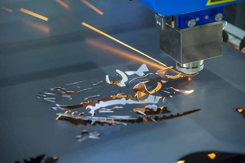
The sheet metal unloading methods mainly include digital punching, laser cutting, shearing machine, mold unloading, etc. Digital punching is the commonly used method at present, laser cutting is mostly used in the sampling stage, which has a high processing cost, and mold unloading is mostly used in high-volume processing.
Below, we mainly introduce the sheet metal material with the number of punches.
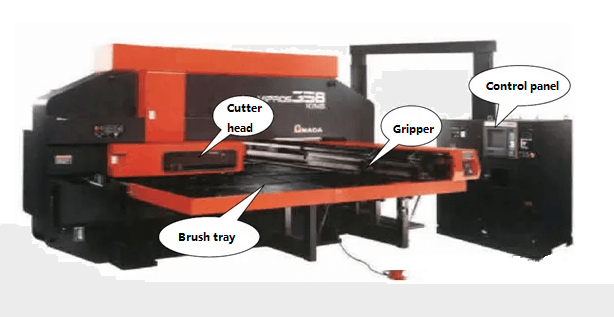
Digital punching, also known as turret punching, can be used for punching, punching, stretching holes, pressure bars, etc., and its processing accuracy can reach +/- 0.1mm.
The thickness of sheet metal that can be processed by digital punching is:
Cold rolled plate, hot rolled plate ≤3.0mm
Aluminum plate ≤4.0mm
Stainless steel plate ≤2.0mm
1. Punching has a minimum size requirement. The minimum size of the punching is related to the shape of the hole, the mechanical properties of the material, and the thickness of the material. (As shown below)
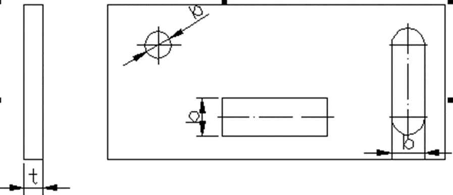
| Material | Circular hole diameter b | Rectangular hole short side width b |
| High carbon steel | 1.3t | 1.0t |
| Mild steel, brass | 1.0t | 0.7t |
| Aluminum | 0.8t | 0.5t |
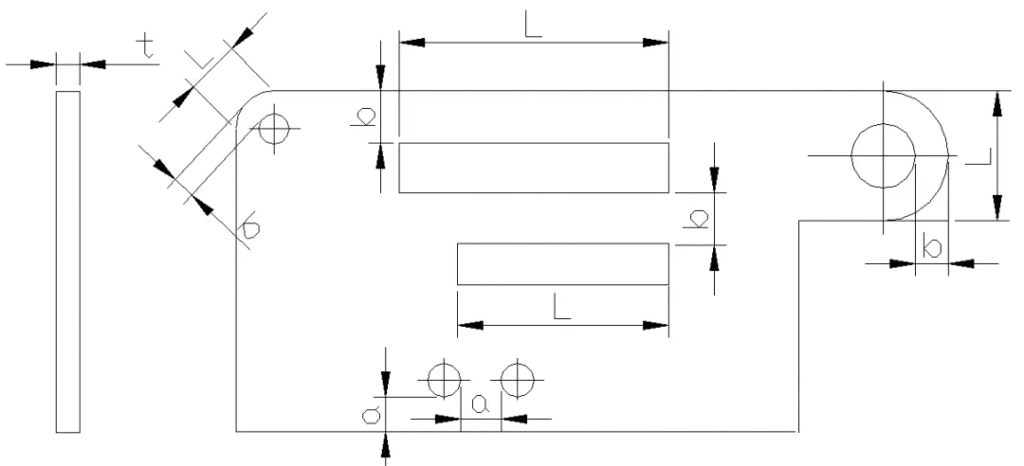
2. Punch hole spacing and hole margins. The minimum distance between the punched edge and the outer shape of a part has certain limitations depending on the shape of the part and the hole. When the punched edge and the outer edge of the part are not parallel, the minimum distance should be no less than the material thickness a = t, when they are parallel, it should be no less than b = 1.5t. (As shown below)
3. When stretching a hole, the minimum distance from the edge is 3T, the minimum distance between two stretching holes is 6T, and the minimum safe distance from the stretching hole to the bending edge (inside) is 3T+R (T is the thickness of the sheet metal, R is the bend radius)
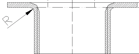
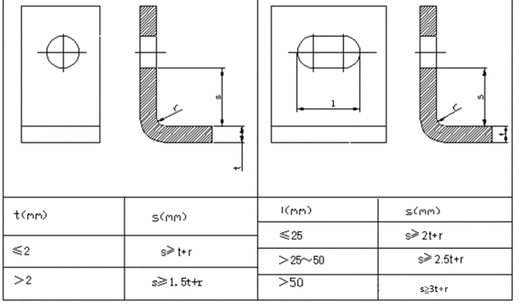
4. When punching holes in bent and drawn parts, a certain distance should be maintained between the hole wall and the straight wall. (As shown in the figure below)
Sheet Metal Processing – Forming
Sheet metal forming primarily involves bending and stretching.
1. Sheet Metal Bending
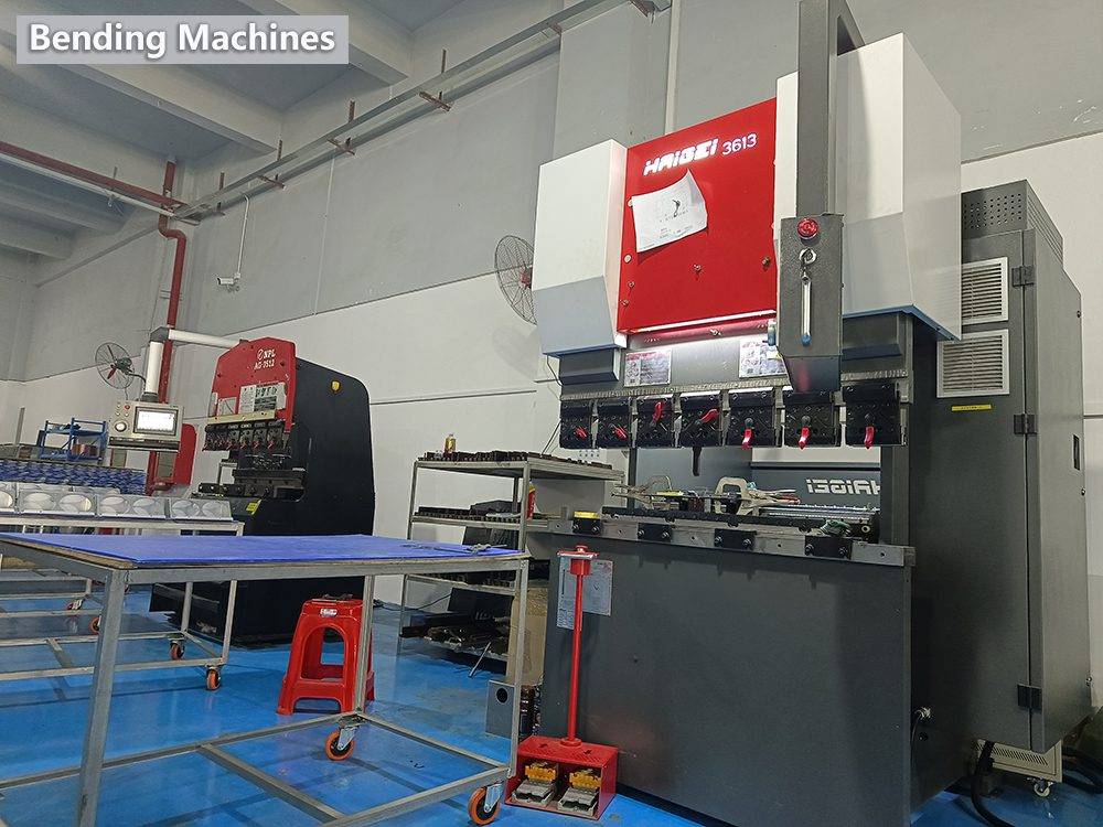
1.1 Sheet metal bending is primarily performed using press brakes.
Precision of press brakes:
First fold: +/- 0.1mm
Second fold: +/- 0.2mm
Second fold: +/- 0.3mm
1.2. Basic principles of bending sequence: Bend from inside to outside, from small to large, first for special shapes, then for general shapes. The previous forming process should not affect or interfere with subsequent processes.
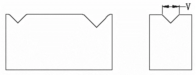
1.3. Common folding knife shapes:

Common V-groove shapes:
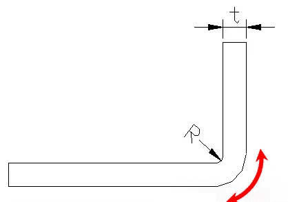
1.4. Minimum Bend Radius for Bending Parts:
When bending a material, the outer corner radius experiences tension, while the inner corner radius experiences compression. For a given material thickness, the smaller the inner radius, the greater the tension and compression. When the tensile stress in the outer corner radius exceeds the material’s ultimate strength, cracks and fractures can occur. Therefore, when designing bent parts, avoid excessively small corner radii. The table below lists the minimum bend radii for commonly used materials.
| Material | Minimum bending radius |
| 08、08F、10、10F、DX2、SPCC、E1-T52、0Cr18Ni9、1Cr18Ni9、1Cr18Ni9Ti、1100-H24、T2 | 0.4t |
| 15、20、Q235、Q235A、15F | 0.5t |
| 25、30、Q255 | 0.6t |
| 1Cr13、H62(M、Y、Y2、Cold Rolling) | 0.8t |
| 45、50 | 1.0t |
| 55、60 | 1.5t |
| 65Mn、60SiMn、1Cr17Ni7、1Cr17Ni7-Y、1Cr17Ni7-DY、SUS301、0Cr18Ni9、SUS302 | 2.0t |
The bend radius refers to the inside radius of the bent part, and t is the wall thickness of the material.
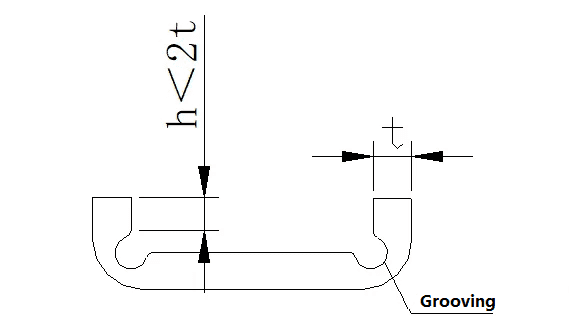
1.5. Straight-edge height of bent parts: Generally, the minimum straight-edge height should not be too small. The minimum height requirement is: h > 2t.
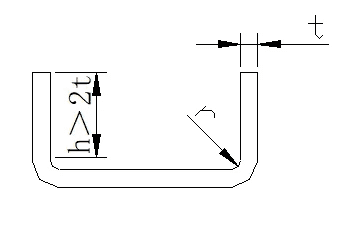
If the straight edge height of the bent part needs to be h≤2t, the bending height must be increased first, and then processed to the required size after bending, or a shallow groove must be processed in the bending deformation area before bending.
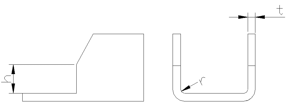
1.6. Height of straight edge with bevel on the bend side: When the bend side has a bevel on the bend side, the minimum height of the side is: h = (2~4) t>3mm
1.7. Hole margin on bent parts: Hole margin: Punch the holes first and then bend them. The holes should be located outside the bending deformation zone to avoid deformation during bending. The distance from the hole wall to the bending edge is shown in the table below.
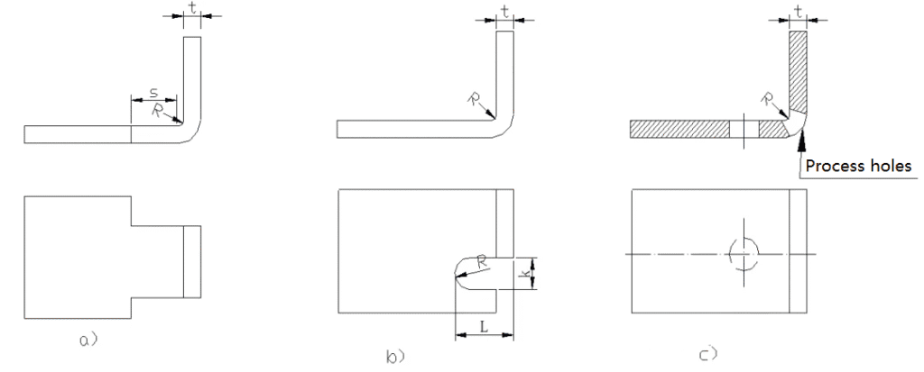
1.8. Process Cuts for Localized Bending:
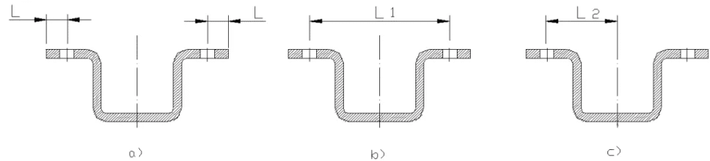
The bending line of a bent part should avoid locations with sudden dimensional changes. When locally bending a specific edge to prevent stress concentration at sharp corners and cracking, the bending line can be moved a certain distance away from the sudden dimensional change (Figure a), or a process groove can be cut (Figure b), or a process hole can be punched (Figure c). Note the dimensional requirements in the diagram: S ≥ R, groove width k ≥ t, groove depth L ≥ t + R + k/2.1.8.
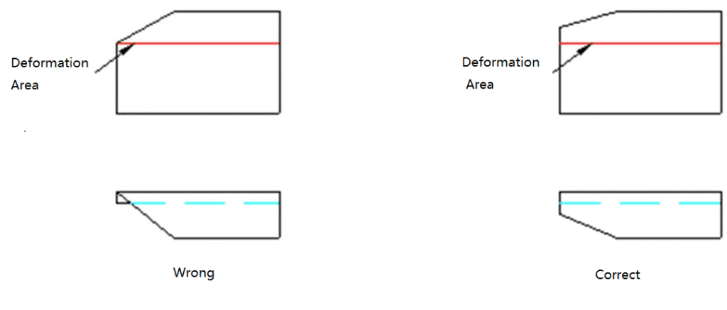
1.9. The bend edge with bevel should avoid the deformation zone
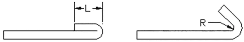
1.10. Design Requirements for Hemming:
The minimum length of the hem (dead edge) is related to the material thickness. As shown in the figure below, the minimum hem length is generally L ≥ 3.5t + R.
Here, t represents the material thickness, and R is the minimum inside bending radius from the previous process step (as shown on the right side of the figure).
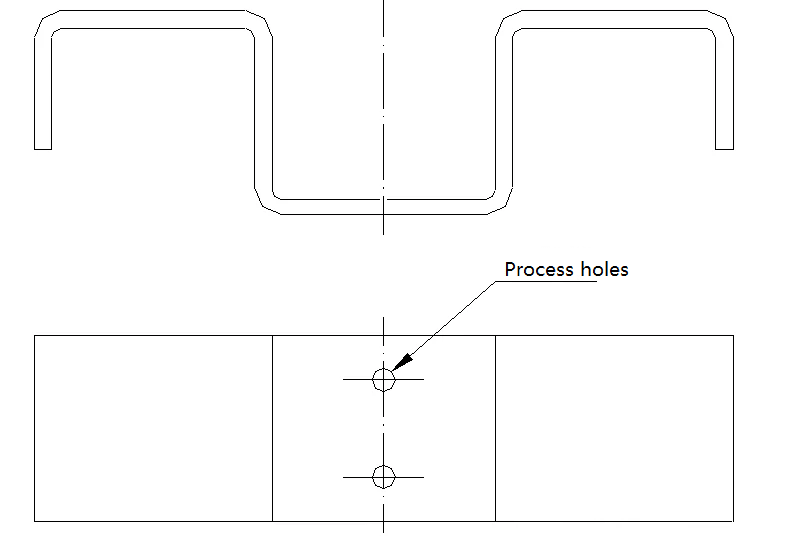
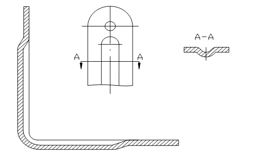
1.11. Added Process Positioning Holes:
To ensure accurate positioning of the blank in the mold and prevent deviation during bending, which could result in scrap, process positioning holes should be added during the design, as shown in the figure below. Parts that undergo multiple bends must use these holes as a positioning reference to minimize cumulative errors and ensure product quality.
1.12. Different marking dimensions and different processability:
As shown in the figure above, a) punching first, then bending, easily ensures L-dimensional accuracy and facilitates processing. b) and c) require bending first and then punching the hole, which is more complex.
1.13. Springback of Bent Parts:
Many factors influence springback, including the material’s mechanical properties, wall thickness, bend radius, and the normal pressure during bending.
The greater the ratio of the bent part’s inner fillet radius to the plate thickness, the greater the springback.
Introducing ribs in the bend area not only increases workpiece rigidity but also helps prevent springback.
2. Sheet Metal Stretching
Sheet metal stretching is primarily accomplished by multiple punching or general punching, requiring various punches or dies.
The shape of the stretched part should be as simple and symmetrical as possible, and should be formed in a single stretching operation whenever possible.
For parts requiring multiple stretching, allowance should be made for surface marks that may form during the stretching process.
While ensuring assembly requirements, a certain degree of slope should be permitted for the sidewalls of the stretched part.
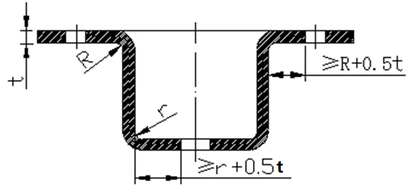
2.1. Fillet Radius Requirements between the Bottom and Straight Wall of the Stretched Part:
As shown in the figure to the right, the fillet radius between the bottom and straight wall of the stretched part should be greater than the sheet thickness, i.e., r1 ≥ t. To ensure smooth stretching, r1 is generally set to (3-5)t. The maximum fillet radius should be less than or equal to 8 times the sheet thickness, i.e., r1 ≤ 8t.
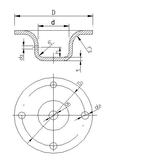
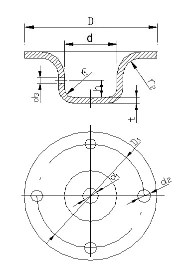
2.2. Fillet radius between the flange and the wall of the stretched part: As shown in the figure on the right, the fillet radius between the flange and the wall of the stretched part should be greater than twice the thickness of the plate, that is, r2 ≥ 2t. In order to make the stretching process smoother, r2 = (5~10)t is generally taken. The maximum flange radius should be less than or equal to 8 times the thickness of the plate, that is, r2 ≤ 8t.
2.3. Fillet Radius between the Flange and Wall of the Stretched Part:
As shown in the figure to the right, the fillet radius between the flange and wall of the stretched part should be greater than twice the plate thickness, i.e., r² ≥ 2t. To ensure smoother stretching, r² is generally set to (5-10)t. The maximum flange radius should be less than or equal to 8 times the plate thickness, i.e., r² ≤ 8t.
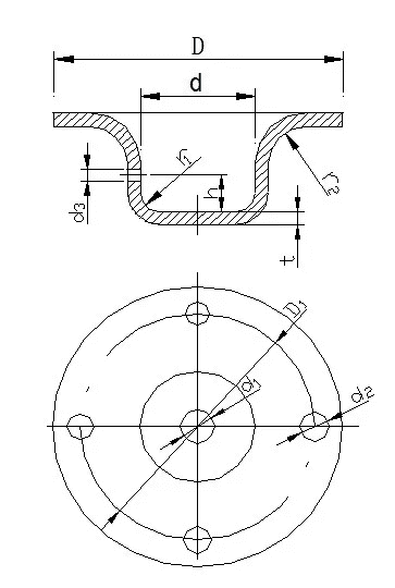
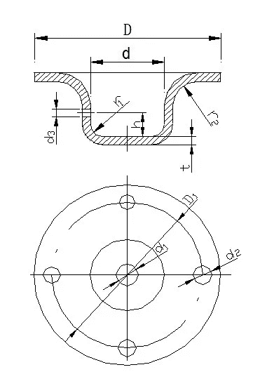
2.4. Inner Diameter of Circular Stretched Parts:
As shown in the figure to the right, the inner diameter of a circular stretched part should be D ≥ d + 10t to prevent wrinkling due to the tight compression of the press plate during stretching.
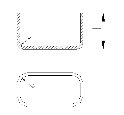
2.5. Fillet Radius Between Adjacent Walls of Rectangular Stretched Parts:
As shown in the figure to the right, the fillet radius between adjacent walls of a rectangular stretching part should be r3 ≥ 3t. To minimize the number of stretches, r3 ≥ H/5 should be used to allow for a single-shot pull.
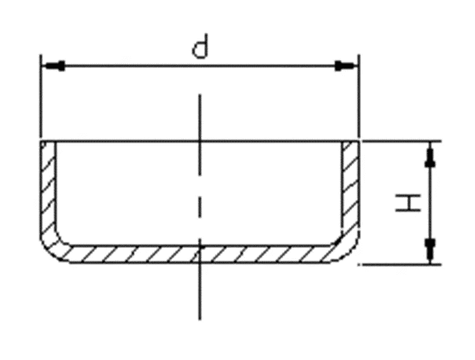
2.6. Required Dimensional Relationship Between Height and Diameter for Circular Flangeless Drawings During Single-Forming:
As shown in the figure to the right, for circular flangeless drawing parts during single-form forming, the ratio of height H to diameter d should be less than or equal to 0.4, i.e., H/d ≤ 0.4.
2.7. Thickness Variation of Stretched Parts:
Due to the varying stress levels experienced at various locations within a stretched part, the thickness of the material after stretching varies. Generally speaking, the center of the bottom maintains its original thickness, while the material becomes thinner at the bottom corners and thicker near the top flange. For rectangular stretched parts, the material becomes thicker at the rounded corners.
When designing stretched products, the dimensions on the product drawing should clearly indicate whether the external or internal dimensions must be maintained, both internal and external dimensions should not be indicated simultaneously.
3. Other Sheet Metal Forming:
Ribs—A rib is formed by pressing a rib onto a sheet metal part to increase structural rigidity.
Louvres—Louvres are commonly used on various covers or housings for ventilation and heat dissipation.
Hole Flanging (Stretch Hole)—Used for threading or to increase the rigidity of an opening.
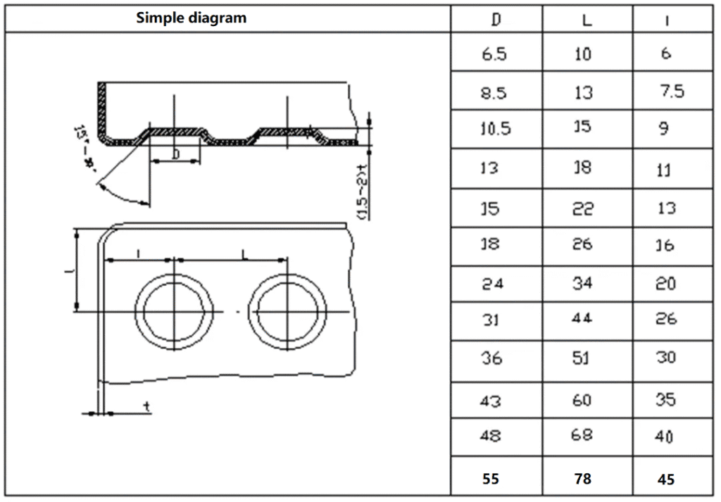
3.1. Ribs: Rib Structure and Dimension Selection
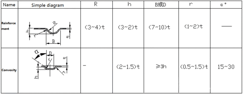
Limit dimensions of convex spacing and convex margins
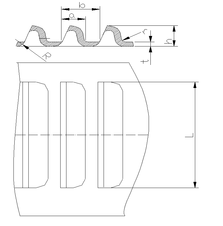
3.2. Venetian Blinds:
The Venetian blinds forming method uses the cutting edge of one side of the punch to cut the material, while the rest of the punch simultaneously stretches and deforms the material, creating an undulating shape with one side open.
Typical structure of a Venetian blind.
Venetian blinds dimension requirements: a ≥ 4t, b ≥ 6t, h ≤ 5t, L ≥ 24t, r ≥ 0.5t.
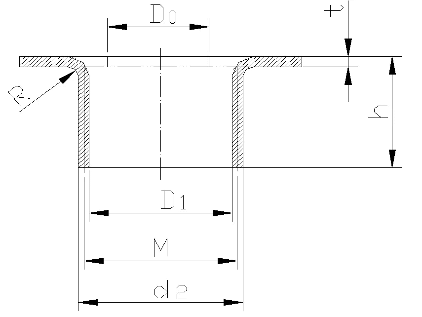
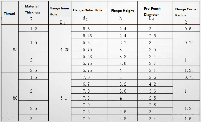
3.3. Hole Flanging (Drawing Holes):
There are many types of hole flanging, the most common of which is internal hole flanging for threading.
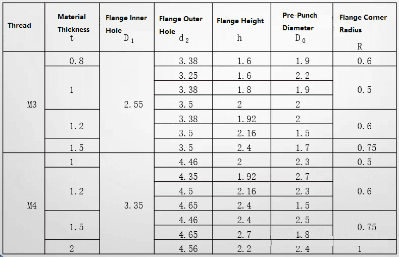
Sheet Metal Fabrication—Other Processing
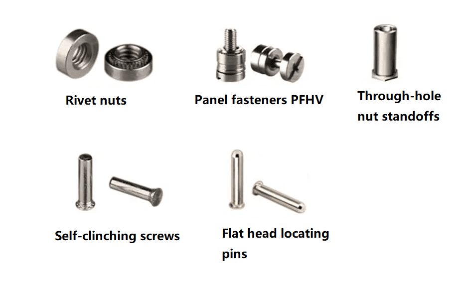
1. Riveting of sheet metal accessories, such as rivet nuts, rivet studs, and rivet guides.
2. Tapping threaded holes in sheet metal.
Sheet Metal Processing – Welding
When designing sheet metal welded structures, adhere to the principle of “symmetrically arranging welds and weld points, avoiding intersections, clustering, and overlaps.” Minor welds and weld points can be interrupted, while major welds and weld points should be connected.
Common welding methods for sheet metal include arc welding and resistance welding.
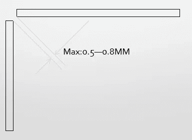
1. Arc Welding
Sufficient space should be provided between sheet metal sheets. The maximum welding gap should be 0.5-0.8 mm, and the weld should be even and smooth.
2. Resistance Welding
The weld surface must be flat, free of wrinkles and springback. The dimensions for resistance spot welding are as follows:
| Plate thicknesst (mm) | Welding spot diameter d (mm) | Minimum distance from solder point to edge f (mm) | Minimum width of welding edge (mm) |
| 0.6-0.79 | 5.0-6.0 | 5 | 10 |
| 0.8-1.39 | 5.5-6.5 | 5-6 | 10-12 |
| 1.4-1.99 | 6.0-7.0 | 7-9 | 14-18 |
| 2.0-2.49 | 6.5-7.5 | 9-10 | 18-20 |
Resistance Welding Spot Spacing
In practical applications, when welding small parts, refer to the data in the table below. When welding large parts, the spot spacing can be increased appropriately, generally not less than 40-50mm. In non-stressed areas, the spot spacing can be increased to 70-80mm.
Plate thickness t, spot diameter d, minimum spot diameter dmin, and minimum distance between spots e. If the plates are of different thicknesses, select the thinnest plate.
| Plate thicknesst t(mm) | Welding spot diameter d(mm) | Minimum solder joint diameter dmin(mm) | Minimum distance between solder joints on the second layer e(mm) | Minimum distance between solder joints on three-layer boards e(mm) |
| 0.6-0.79 | 5.0-6.0 | 3.5 | 12-16 | 15-20 |
| 0.8-1.39 | 5.5-6.5 | 4.0 | 16-25 | 20-33 |
| 1.4-1.99 | 6.0-7.0 | 4.5 | 25-40 | 33-50 |
| 2.0-2.49 | 6.5-7.5 | 5.0 | 40-50 | 50-63 |
Number of Layers and Thickness Ratio for Resistance Welding
Resistance spot welding typically involves two layers, with a maximum of three. The thickness ratio of each layer at the weld joint should be between 1/3 and 3.
If three-layer sheet metal welding is necessary, first check the thickness ratio. If it is reasonable, welding is permitted. If not, consider creating process holes or notches, welding two layers, and staggering the weld points.
Sheet Metal Fabrication – Connection Methods
This section focuses on the connection methods used in sheet metal fabrication, primarily riveting, welding (described above), punch riveting, and TOX riveting.
1. Rivet Riveting: This type of rivet is often called a pull rivet. Riveting two sheets together using a pull rivet is called a pull rivet. Common rivet shapes are shown in the figure below:
2. Welding
3. Hole-and-Rivet
One part has a hole-and-recess, the other has a countersunk hole. A riveting die creates a non-detachable connection. Advantages: The hole-and-recessed countersunk hole provide inherent positioning. Riveting strength is high, and die-based riveting efficiency is also relatively high.

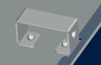
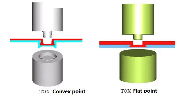
4. TOX Riveting:
A simple punch presses the joined parts into a die. Further pressure causes the material inside the die to “flow” outward. The result is a rounded joint with no sharp corners or burrs. This joint also maintains corrosion resistance, even on coated or painted panels, as the coating and paint deform and flow with the material. The material is squeezed outward and into the panel on the die side, forming the TOX joint. See the figure on the following page:
Sheet Metal Processing – Surface Treatment
Surface treatment of sheet metal can provide both corrosion protection and decorative effects. Common surface treatments for sheet metal include powder coating, electrogalvanizing, hot-dip galvanizing, surface oxidation, surface brushing, and silk-screen printing.
Before surface treatment, remove oil, rust, welding slag, and other stains from the sheet metal surface.
- Powder Coating:
Sheet metal surface coatings can be applied using liquid paint or powder coating. Powder coating is commonly used. Using methods such as powder spraying, electrostatic adsorption, and high-temperature baking, a layer of coating in various colors is applied to the sheet metal surface to enhance its appearance and improve its corrosion resistance. This is a common surface treatment method.
Note: Color variations between different manufacturers will occur, so sheet metal of the same color on the same equipment should be coated by the same manufacturer whenever possible.
- Electrogalvanizing and Hot-Dip Galvanizing:
Galvanizing is a commonly used surface treatment for sheet metal and can also enhance its appearance. Galvanizing can be divided into electrogalvanizing and hot-dip galvanizing. Electrogalvanizing has a brighter, smoother appearance and a thinner zinc coating, making it more commonly used.
Hot-dip galvanizing produces a thicker zinc coating and a zinc-iron alloy layer, offering superior corrosion resistance compared to electrogalvanizing.
- Surface Oxidation:
This section focuses on surface anodizing of aluminum and aluminum alloys.
Surface anodizing of aluminum and aluminum alloys can produce various colors, providing both protective and decorative effects. It also creates an anodic oxide film on the surface of the material, which has high hardness and wear resistance, as well as excellent electrical and thermal insulation properties.
- Surface Brushing:
The material is placed between the upper and lower reels of a wire drawing machine. Abrasive belts are attached to the reels. Driven by a motor, the material passes through the upper and lower belts, creating a series of marks on the surface. The marks vary in thickness depending on the type of abrasive belt. These marks are primarily used to enhance the appearance. Wire brushing is generally considered a surface treatment for aluminum.
- Silkscreen Printing:
Silkscreen printing is a process for applying various markings to a material’s surface. There are two general methods: flatbed silkscreen printing and pad printing. Flatbed silkscreen printing is primarily used on flat surfaces, but pad printing is often used for areas with deep recesses.
Silkscreen printing requires a screen printing mold.
Processing Range of Common Processing Equipment
| Machine Type | Brand & Model | Work Area / Specs | Accuracy & Tolerances | Special Features |
| Laser cutting machine | TRUMPF L2530 | Length x Width: 2500 x 1250 mm Thickness: Iron plate 15mm Aluminum plate 5mm Stainless steel 6mm | Positioning accuracy ±0.1mm Repeatability ±0.03mm Secondary positioning ±0.15mm | – |
| NC punch press | FINNPOWER A-5-25 | Length x Width: 2530 x 1270 mm Thickness: Iron plate 3mm Aluminum plate 5mm Stainless steel 2.5mm | Positioning accuracy ±0.1mm Repeatability ±0.03mm Secondary positioning ±0.15mm | 30 knives can be loaded at a time, 4 rotary knives |
| NC folding machine | AMADA RG-100 | Length: 3100 mm | Positioning accuracy ±0.1mm Operational accuracy ±0.2mm Secondary positioning ±0.3mm | – |
| NC shearing machine | SAFAN | Length: 3100 mm Thickness: Iron 6.4mm Stainless steel 4mm | Positioning accuracy ±0.1mm Straightness ±0.2mm | – |
YPMFG’s Sheet Metal Fabcriation
We provide comprehensive sheet metal fabrication services, covering cutting, bending, stamping, punching, welding, and assembly.


