In the mold industry, especially the plastic mold industry, EDM is a very important process. There are many deep grooves and narrow slits, and complex cavities on the mold profile, which are difficult to process with milling machine tools, and sometimes there are a lot of such areas, which require the design of a large number of electrodes for EDM.
Table of Contents
Designing electrodes means splitting a product into several discharge parts according to the difficulty of processing its shape. In some large companies, there is a group specializing in the design of electrodes, enterprises often “design electrodes” called “electrode dismantling”. Electrode design is good or bad directly affects the mold processing speed and quality. At present, many CAD / CAM software programs provide a powerful electrode design function.
1. Structural Forms of Electrodes
(1) In terms of the composition of the electrode, there are two types of structures: the integral electrode and the patchwork electrode.
1) Integral electrode. The whole electrode is machined from one piece of material, which is the most commonly used structural form. For larger electrodes, in order to reduce the mass and prevent excessive load on the spindle, it can be drilled or hollowed out on the end face. For small volume, easy to deform the electrode, in the effective part of the length of the upper part of the cross-section size increases.
2) assembled electrode complex shape of the electrode as a whole, processing difficulties, often divided into several pieces, respectively, and then assembled into a whole after processing. The patchwork electrode can save material and is easy to manufacture. In the manufacture of the electrode should ensure that the position between the inlays should be ensured to be accurate, with a close and solid.
(2) In terms of the shape of the electrode, there are two structural forms: a 2D electrode and a 3D electrode.
1) 2D electrode The electrode molding part is a through shape, a simple two-dimensional entity. This type of electrode is generally manufactured by conventional milling (turning, milling) or EDM wire-cutting.
2) 3D electrode The electrode molding part has a non-through part and is a complex three-dimensional entity. The manufacturing of this type of electrode can only be accomplished by the multi-axis machining method of CNC machine tools.
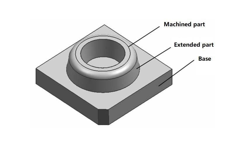
(3) From the point of view of the role of each part of the electrode, the electrode structure can be divided into the machining part, the extension part, and the base.
1) The machining part is the part used for electric discharge machining, and the shape of this part is the opposite of the shape of the cavity.
2) Extension part is the part that extends at the edge of the machining part according to a certain shape, which is used to ensure the shape of the machining part and connect the machining part and the base.
3) Base is a reference table used for calibration and positioning during EDM machining.
2. Experience in Designing Electrodes
(1) Before designing electrodes, we should fully understand the structure of the mold. Separate the rubber position, the inserted broken position, the leaning broken position, the pillow position, etc., of the mold, confirm which parts need to be discharged, and whether the die nut and inserts are to be assembled and discharged.
(2) When designing electrodes, it is necessary to follow a certain order in order to prevent the electrodes from being dismantled. This is very important for the electrode design of complex molds.
(3) The design of electrodes should consider the production of electrodes. Designed electrodes should be easy to produce, preferably using only one processing method can be completed. Such as CNC milling complex electrode production is very convenient, but also easy to ensure the accuracy of the electrode.
(4) for the product has the appearance and prismatic requirements of the mold, you can give priority to the electrode design for a time can be processed as a whole cavity structure; but also pay attention to, EDM in the processing of the existence of the “area effect”, in the electrode area is relatively large, and the depth of machining is deeper, chip removal difficulties, the overall electrode should be split into several electrode For sub-processing, otherwise there will be unstable discharge, slow processing speed, precision is difficult to ensure the bad situation; sometimes the overall electrode processing is difficult, there is a dead space that can not be processed, or is not good processing, the tool required is too long or too small, you can consider more than one electrode, and sometimes the local need to clear the corner of the electrode.
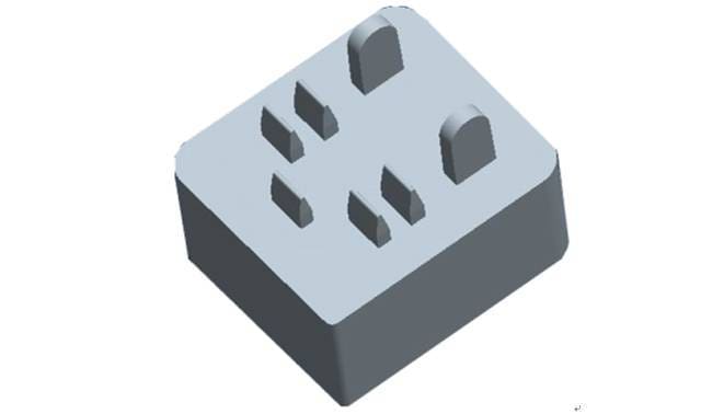
(5) The sharp corners, edges and other raised parts of the electrode are faster than the flat parts in EDM. In order to improve the precision of EDM, the electrode can be broken down into a main electrode and a sub-electrode. When designing the electrode, the main electrode can be used to process the main part of the cavity or hole, and then the sub-electrode can be used to process the sharp corners, narrow slits and other parts.
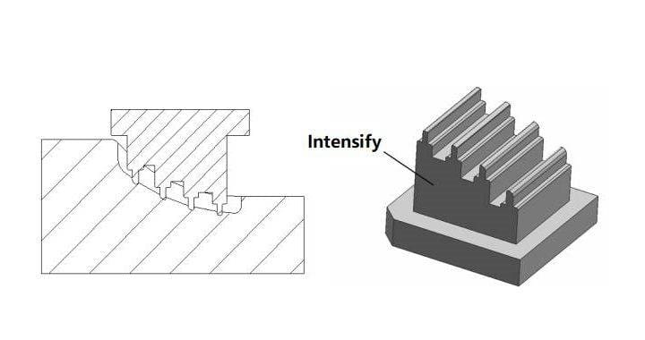
(6) For some thin, small, high and low drop electrodes, electrodes in CNC milling and EDM are very easy to deform, the design of the electrode should be used to strengthen the electrode to prevent deformation of the method. The following are typical examples of reinforced electrodes.
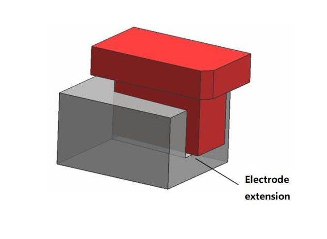
(7) The electrode must be extended a certain size in the direction of the machining part to ensure that there is no protruding small tendon in the mouth after machining out of the work station.
(8) The parts of the electrode that need to be avoided must be avoided to avoid unwanted discharges outside the machined parts in the EDM process.
(9) Consideration should be given to reducing the number of electrodes when designing electrodes. It can be reasonable to combine some different machining parts on the workpiece as a whole or realize the machining of multiple positions by moving coordinates; multiple identical machining parts on the workpiece can be machined by moving the coordinates of the electrodes.
(10) The design of electrodes should be designed to separate parts with different processing requirements in order to meet the respective processing requirements. Such as mold parts in the assembly parts and molding parts of the surface roughness requirements and dimensional accuracy are not the same, so these parts of the electrode can not be mixed in design together.
(11) to the electrode design suitable base. The base is the benchmark for correcting the electrode and positioning in EDM, and it is also the processing benchmark for multiple processes of the electrode, such as in the processing of the corner parts of the tool on the electrode to be removed by wire cutting. It is necessary to use the base for positioning. In addition, the base is best designed to facilitate the installation of electrodes to identify the direction of the reference angle.
(12) Consider the EDM process when designing the electrode. Select Z-axis servo processing or lateral processing, or multi-axis linkage processing; electrode to facilitate the clamping and positioning; according to the specific circumstances of the opening of the chip removal, exhaust holes.
(13) Determination of the number of electrodes. Determination of the number of electrodes depends mainly on the shape of the workpiece and the number of machining, and secondly, we must take into account the material of the workpiece, the depth of machining and the machining area.
(14) There are two ways to design the base of the electrode. One method is to design the base on the basis of the maximum shape of the electrode machining part of the uniform expansion, the result is that the base, as the basis of the X, Y, Z coordinate value, is often a small number. The second method is to determine an integer for the X, Y, Z coordinate value of the base reference first. Obviously, the second method can avoid the EDM operator from complex fractional misreading of the situation.
(15) A set of molds after the completion of all electrode design, should fill out the bill of materials (according to the electrode requirements to confirm the electrode blank length, width, height and electrode number, material), to arrange for the production of electrodes, the design of EDM drawings (discharge coordinates, processing requirements and details of the notes).
In short, the design of electrodes should be considered comprehensively, seize the key points, under the premise of ensuring the quality of EDM processing, as far as possible to improve processing efficiency and reduce processing costs.
3. Concept of Electrode Drawdown
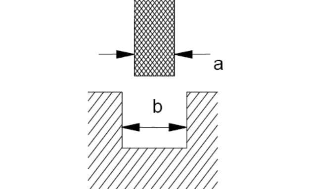
There is a discharge gap between the workpiece and the electrode in the EDM process. In order to get the required machining size, the electrode size should be smaller than the size of the cavity to be machined, i.e., the electrode is scaled up to a certain size, and the scaled-down size is called the electrode scaling capacity. As shown in the figure below, electrode bilateral scaling = b-a, electrode unilateral scaling = (b-a)/2, most occasions use the electrode scaling refers to the bilateral value.
4. Mode of Electrode Scaling Size
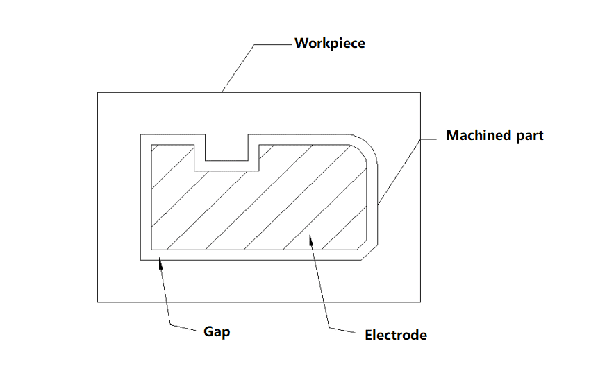
(1) Overall inward or outward expansion
As shown in the figure below, the gap between the electrode and the machined part is equal in all positions. This type of electrode scaling is mainly applicable to complex 3D electrodes, which are usually scaled by CNC (or wire-cutting) overcutting, and they only need to be corrected, avoiding the errors that may be caused by artificial scaling.
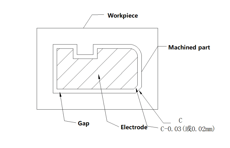
(2) Separate the scaling gap between the straight part, and arc, and the chamfer
As shown in the figure below, the electrode and the machining part have unequal clearance values at one or more positions. The straight part is scaled by one offset according to the theory, and the arc or chamfer is 0.03~0.02㎜ larger or smaller than the actual size of the workpiece (when the workpiece is outer R, the electrode R size is larger than the actual size; when the workpiece is inner R, the electrode R size is smaller than the actual size). The separate scaling gap method is mainly applicable to 2D electrodes and simple 3D electrodes.
(3) Scaling method of electrode scaling for special stations.
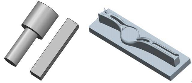
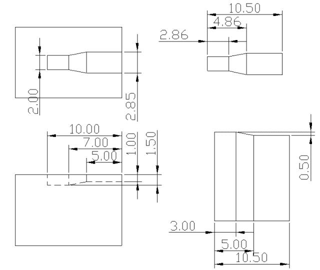
(Example 1) As shown in the figure below: the left side is the workpiece, and the right side is the electrode.
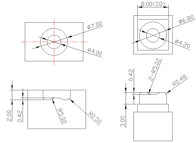
In the above figure, Φ7.00 and Φ4.00 are reduced by 0.10㎜ on one side, and in the main view, R5.00 and R0.50 are reduced by 0.02㎜ on one side, and 0.42 is the relevant dimension, so this dimension is guaranteed to be unchanged on the electrode. 2.00 dimension is in the open direction, so the electrode is extended upward to 3.0, and if this electrode adopts the whole inward shrinkage, the dimension of the electrode corresponding to 4.00 on the workpiece will still be equal to 4.00, while R0.50 dimension will be R0.40. 4.00, while R0.50 is R0.40. When working with this electrode, it is not possible to carry out translational machining, and the depth and sides will be left with more excess, which will inevitably lead to an exponential increase in the machining time during finishing, and the dimensions will not be guaranteed well.
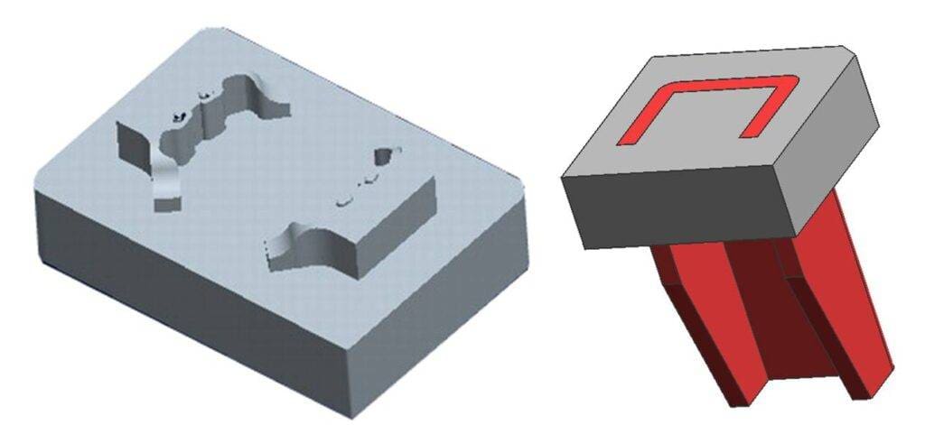
(Example 2) As shown below, the workpiece is on the left, electrode is on the right.
As can be seen from the above figure, the discharge station of the workpiece includes an open station and a closed station, so when the electrode is scaling the gap, the contour shape of the electrode and the bottom surface have to be separated to scale the gap. The relevant dimensions of the open part are equal to the size of the station, and the outermost part of the electrode must be extended by one size to ensure that the results of machining achieve the intended purpose; the closed size of the bottom surface corresponds to the scaling of the corresponding gap, and the same open part should be extended accordingly; the depth of the machining direction of the breakage size is equal to the size of the station. (This can be understood by comparing the dimensions of the corresponding stations and electrodes in the figure above.)
(Example 3) As shown in the figure below: the workpiece is on the left.
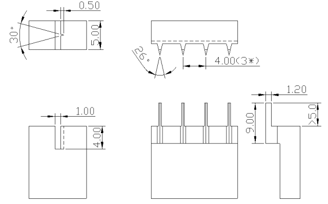
This workpiece discharge station looks simple, but because of the actual discharge factors and other aspects, if the electrode is designed according to the theoretical 30.0 °, to ensure the size of 0.50 in the figure, the actual machining out of the angle will usually be larger than 30.0 °. Mainly because of electrical discharge machining in the angular part of the largest consumption, and the electrode in the molding of the sharp corners has been partially melted off, so in the processing, to ensure that the size of 0.50, 30.0 ° will be too large. Therefore, according to the empirical value, the angle of the electrode should be about 2.0° smaller than that of the workpiece on one side.
5. How to Determine the Amount of Electrode Retraction
Determine the amount of electrode scaling. The main factors to consider: processing shape, processing size, processing allowance, processing accuracy requirements, processing surface roughness requirements, electrode and workpiece material.
(1) CNC EDM rough, medium and finish machining electrode unilateral scaling generally takes 0.30mm, 0.15mm, and 0.1mm.
(2) The processing area is relatively small for EDM occasions; the electrode scaling should be small. The processing area is relatively large for EDM occasions; the electrode scaling should be large.
(3) The depth value is relatively large EDM occasions, the electrode scaling volume should be taken larger, in order to avoid the roughing efficiency being low and the secondary discharge caused by the workpiece mouth size being overdimensioned.
(4) When the workpiece is made of cemented carbide, the discharge gap in actual machining is only about half of that of a steel workpiece, so the determined electrode scaling volume should be smaller.
(5) The electrode scaling volume largely determines the processing speed. If the discharge energy is larger, the discharge gap will also be larger; vice versa. Larger discharge energy processing speed will be faster. If the electrode shrinkage increases, the processing speed will also be doubled.


