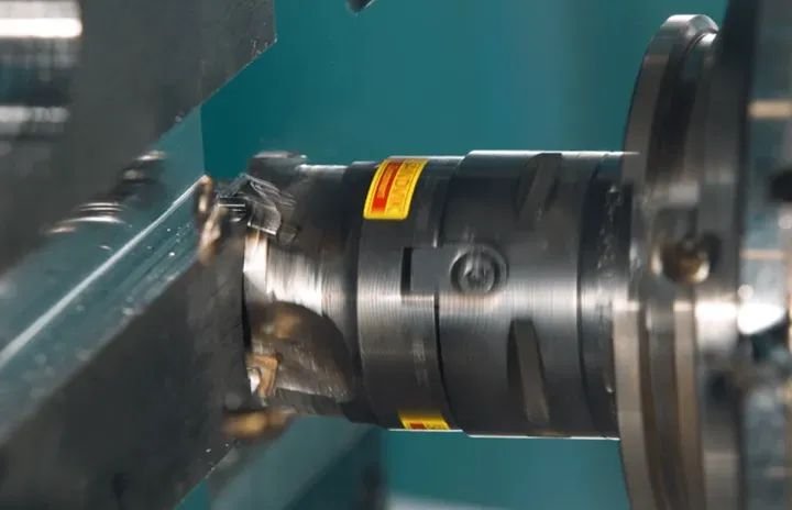
01 Turning
Turning can be divided into different types, including external turning, internal turning, face turning, and thread turning.
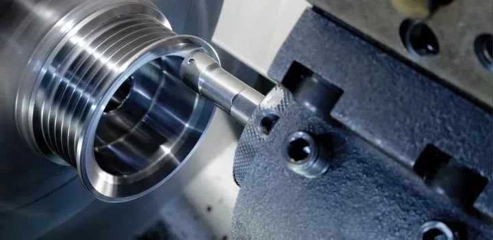
In turning, the workpiece rotates to generate the main cutting action. When the tool moves parallel to the workpiece’s rotational axis, an internal or external cylindrical surface is formed. If the tool moves along an inclined line at a certain angle to the rotational axis, a conical surface is generated. On copying lathes or CNC lathes, by precisely controlling the tool’s feed path along a specific curve, a specific rotational curved surface can be produced. Additionally, using a forming tool with transverse feed can also machine rotational curved surfaces. Turning is also suitable for machining threaded surfaces, end faces, and eccentric shafts.
Generally, the machining accuracy of turning can reach IT8 to IT7, with a surface roughness range of 6.3 to 1.6 micrometers. In precision turning, the machining accuracy can reach IT6 to IT5, and the surface roughness can be reduced to 0.4 to 0.1 micrometers. Turning offers high production efficiency, a relatively stable cutting process, and requires simple tools.
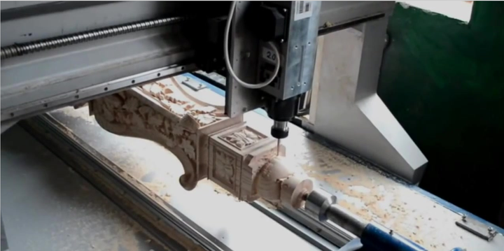
02 Milling
Milling involves removing material from the workpiece surface using a rotating tool. Through precise control of the tool’s movement path, it can produce parts with complex structures such as planes, concave-convex surfaces, and gears. Milling processes include slab milling, vertical milling, face milling, gear milling, and contour milling, each designed for specific machining needs to meet different production requirements.
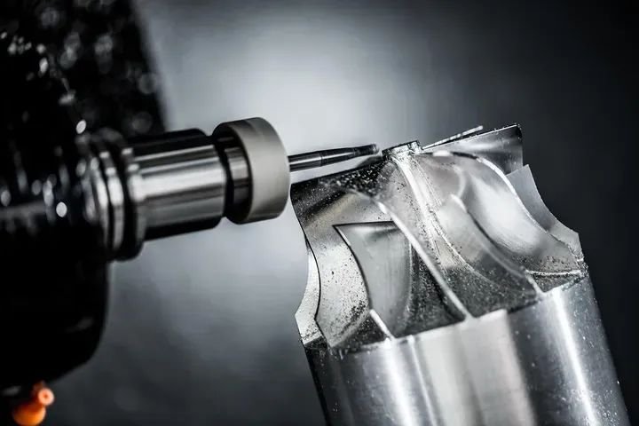
In milling operations, the tool’s rotation constitutes the main cutting action. During horizontal milling, the plane is formed by the cutting edges on the outer circular surface of the milling cutter; during vertical milling, the plane is formed by the end edges of the milling cutter. Increasing the milling cutter’s rotational speed can significantly accelerate the cutting speed and improve production efficiency. However, since the milling cutter teeth experience impact when cutting into and out of the material, vibrations may occur during cutting, limiting the improvement of the machined surface quality. This impact can also accelerate tool wear or even damage, especially for carbide inserts, which may crack. Fortunately, the tool is cooled for most of the time when separated from the workpiece, so the heat dissipation condition is relatively good.
According to the relationship between the main movement speed of the milling cutter and the workpiece feed direction, milling can be divided into climb milling and conventional milling. In milling, the horizontal component of the milling force is consistent with the workpiece feed direction. Due to the usual clearance between the workpiece table feed screw and the fixed nut, the cutting force may cause the workpiece and table to move forward together, leading to a sudden increase in feed and tool damage. When milling workpieces with high surface hardness (such as castings or forgings), climb milling causes the tool teeth to first contact the workpiece’s hard skin, accelerating milling cutter wear. In contrast, conventional milling avoids the workpiece shifting that may occur in climb milling. However, conventional milling has its disadvantages: since the cutting thickness gradually increases from zero, the cutting edge initially slides and squeezes on the hardened machined surface, accelerating tool wear. At the same time, the milling force in conventional milling tends to lift the workpiece, easily causing vibrations.
The machining accuracy of milling generally reaches IT8—IT7, with a surface roughness of 6.3—1.6 μm.
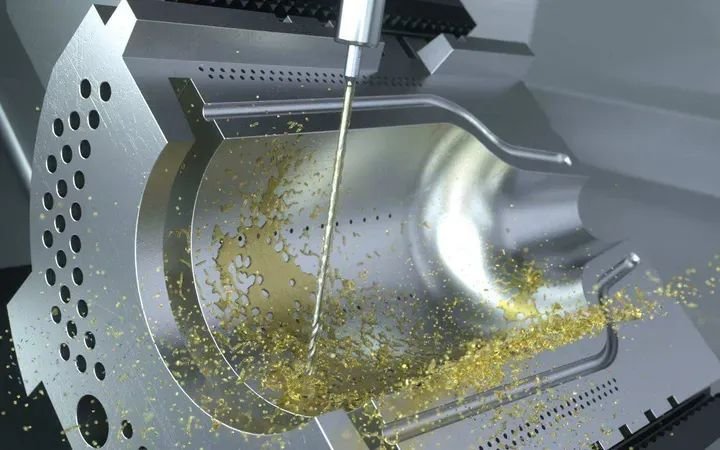
Conventional milling is mainly limited to plane machining, but specific curved surfaces can also be machined using special forming milling cutters. CNC milling machines, however, use software and CNC systems to coordinate the movement of multiple axes according to predefined relationships, enabling the milling of complex and varied curved surfaces. In such cases, ball-end milling cutters are typically used. For machining complex-structured workpieces such as impeller blades, mold cores, and cavities, the application of CNC milling machines is particularly important, significantly improving the efficiency and accuracy of such workpiece machining.
03 Dirlling
Drilling is a process that uses a rotating drill bit to cut through workpiece materials and create holes with specific diameters and depths. This technology is widely used in manufacturing, construction, and maintenance industries. Depending on the specific application scenario, drilling can be subdivided into conventional drilling, center drilling, deep-hole drilling, and multi-axis drilling.
Conventional drilling typically uses a drill bit with spiral cutting edges and is suitable for small holes and regular drilling operations. Center drilling involves pre-drilling a small hole on the workpiece surface as a positioning reference before switching to a larger drill bit to ensure the precise location of the larger hole. Deep-hole drilling is used for machining holes with greater depths, requiring specialized drill bits and cooling techniques to ensure machining accuracy and quality. Multi-axis drilling technology uses multiple drill bits simultaneously at different angles for synchronous drilling, making it ideal for scenarios requiring the machining of multiple holes at once.
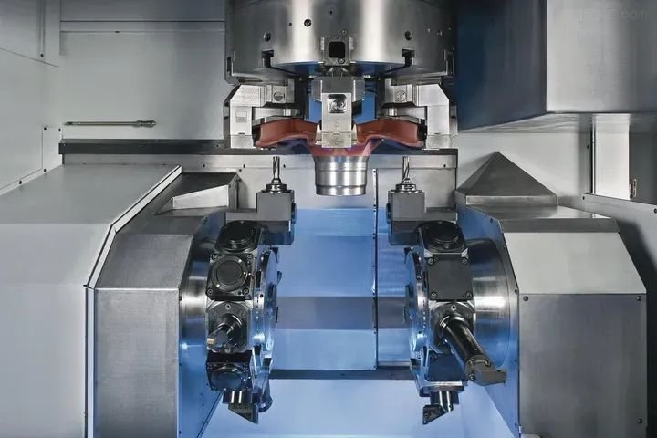
04 Grinding
Grinding involves using abrasive tools to gradually cut or abrade the workpiece surface material to achieve the desired shape, specifications, and surface finish. This technology is widely used in applications requiring high part precision and surface quality, such as mold manufacturing, precision mechanical parts processing, and tool preparation.
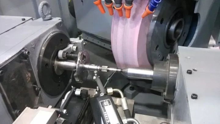
Grinding techniques can be divided into surface grinding, cylindrical grinding, internal grinding, and profile grinding. Surface grinding is mainly used to process flat workpiece surfaces to achieve smooth surfaces and precise dimensions. Cylindrical grinding focuses on the external surface machining of cylindrical workpieces (such as shafts and pins). Internal grinding is used for machining the internal surfaces of holes (such as inner bores and shaft holes). Profile grinding is suitable for machining complex-shaped profiles, such as the cutting edges of molds and tools.
05 Boring
Boring is primarily used for precision machining of internal circular holes in workpieces. It involves rotating the tool to cut within an existing hole to achieve the required precise dimensions and flatness. Unlike drilling, which creates holes directly on the workpiece surface, boring completes the cutting by inserting the tool deep into the workpiece. Boring techniques are divided into manual and CNC types. Manual boring is typically suitable for small-batch production or simple machining needs, while CNC boring achieves automated high-precision machining through pre-programmed cutting paths, feed rates, and tool rotation speeds.
06 Planing
Planing is a process that uses a planer tool to cut material from the workpiece surface to obtain flat surfaces, precise dimensions, and high-quality surface finishes. This technology is widely used for machining flat surfaces of large workpieces, such as machine tool bases and beds, to provide precise mating surfaces.
The planing process typically consists of roughing and finishing stages. During roughing, the planer tool removes material rapidly with a large cutting depth; during finishing, the cutting depth is reduced to achieve higher surface quality and dimensional accuracy.
Planing techniques can be divided into manual and automatic types. Manual planing is suitable for small-batch production and simple machining tasks, while automatic planing uses automated machine tools to control the movement of the planer tool, ensuring process stability and efficiency.
It is worth noting that the reciprocating linear motion of the tool during planing constitutes the main cutting action. Therefore, planing speed is relatively slow, resulting in lower productivity. Nevertheless, the planing process is smoother than milling, with machining accuracy typically reaching IT8 to IT7 and surface roughness ranging from Ra6.3 to 1.6 micrometers. In precision planing, the flatness can reach 0.02 mm/1000 mm, and the surface roughness can be reduced to 0.8 to 0.4 micrometers.
07 Broaching
Broaching is a process in which a broaching tool gradually penetrates the workpiece for cutting to shape complex internal contours of the workpiece. It is often used to manufacture complex geometric shapes such as contours, grooves, and holes in workpieces and can achieve high machining accuracy and excellent surface finishes, making it suitable for scenarios with strict requirements for part precision and surface quality. Broaching processes are mainly divided into surface broaching, profile broaching, groove broaching, and hole broaching.
Surface broaching is specifically used to machine flat workpiece surfaces to obtain smooth surfaces and precise dimensions. Profile broaching is used for machining complex contour shapes, such as molds and various precision parts. Groove broaching is suitable for manufacturing grooves and slots, where the cutting edges penetrate the workpiece and cut along its surface. Hole broaching focuses on machining the internal contours of holes, with the cutting edges extending into the hole to machine its inner surface.
08 Special Processing
Special processing methods refer to a series of processing methods that differ from traditional cutting methods and use chemical, physical (electrical, acoustic, optical, thermal, magnetic), or electrochemical methods to machine workpiece materials.
These methods include chemical machining (CHM), electrochemical machining (ECM), electrochemical mechanical machining (ECMM), electrical discharge machining (EDM), electrical contact machining (RHM), ultrasonic machining (USM), laser beam machining (LBM), ion beam machining (IBM), electron beam machining (EBM), plasma machining (PAM), electro-hydraulic machining (EHM), abrasive flow machining (AFM), abrasive jet machining (AJM), liquid jet machining (HDM), and various hybrid machining processes.
Electrical Discharge Machining (EDM)
Electrical discharge machining (EDM) is a non-traditional machining method that uses the high temperature generated by instantaneous spark discharge between a tool electrode and a workpiece electrode to erode the workpiece surface material. The core components of an EDM machine include a pulse power supply, an automatic feeding device, a machine tool body, and a working fluid circulation and filtration system. During machining, the workpiece is securely mounted on the machine tool’s worktable.
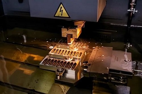
The pulse power supply provides the necessary energy for the machining process, with its positive and negative poles connected to the tool electrode and the workpiece, respectively. As the tool electrode approaches the workpiece under the drive of the automatic feeding device and forms a gap in the working fluid, the inter-electrode voltage breaks down the gap, triggering a spark discharge and releasing enormous heat. The local material on the workpiece surface rapidly heats up (exceeding 10,000°C) due to absorbing this heat, melting or even vaporizing, and eventually being eroded, leaving a tiny pit.
To ensure the smooth progress of the machining process, the working fluid circulation and filtration system plays a key role. It forces clean working fluid to flow through the gap between the tool electrode and the workpiece at a certain pressure, promptly removing the electro-erosion products and filtering them out of the working fluid. With multiple discharges, numerous pits accumulate on the workpiece surface.
Driven continuously by the automatic feeding device, the tool electrode descends, and its contour shape is gradually “copied” onto the workpiece. Although the tool electrode material is also eroded during machining, its erosion rate is much lower than that of the workpiece material. Using a tool electrode with a special shape, an EDM forming machine can machine workpieces with corresponding shapes.
Applications:
① Machining hard, brittle, tough, soft, and high-melting-point conductive materials
② Machining semiconductor materials and non-conductive materials
③ Machining various shaped holes, curved holes, and micro-holes
④ Machining various three-dimensional curved surface cavities, such as the dies of forging dies, casting dies, and plastic molds
⑤ Used for cutting, severing, surface strengthening, engraving, and printing nameplates and marks.
Wire electrical discharge machining (WEDM) uses a wire electrode to machine two-dimensional contour-shaped workpieces.
Electrochemical Machining (ECM)
Electrochemical machining is a technology that uses electrochemical principles, particularly the anodic dissolution of metals in electrolytes, for workpiece shaping. In this process, the workpiece is connected to the positive pole of a DC power supply, while the tool is connected to the negative pole, with a tiny gap (typically 0.1 mm to 0.8 mm) maintained between them.
Meanwhile, an electrolyte solution at a certain pressure (0.5 MPa to 2.5 MPa) flows through this gap at high speed (flow rate 15 m/s to 60 m/s). As the tool cathode continuously feeds toward the workpiece, the part of the workpiece surface opposite the cathode gradually dissolves according to the shape of the cathode. The electrolysis products generated during this dissolution are rapidly carried away by the high-speed flowing electrolyte.
Therefore, as machining progresses, the shape of the tool cathode is “copied” onto the workpiece, achieving precise shaping of the workpiece.
Characteristics:
① Low working voltage and high working current
② Capable of machining complex-shaped surfaces or cavities with simple feeding movements in one step
③ Suitable for machining difficult-to-cut materials
④ Higher productivity, approximately 5–10 times that of EDM
⑤ No mechanical cutting force or heat during machining, suitable for machining deformable or thin-walled parts
⑥ Average machining tolerance can reach ±0.1 mm
⑦ Requires multiple auxiliary devices, occupies a large floor area, and has high costs
⑧ The electrolyte corrodes machine tools and easily pollutes the environment.
Applications:
Electrochemical machining is mainly used for machining shaped holes, cavities, complex profiles, small-diameter deep holes, rifling, deburring, and marking.
Laser Machining
A laser machining machine is a key device for performing laser machining on workpieces, primarily consisting of a laser, a power supply, optical components, and a mechanical system. Among these components, the laser (common types include solid-state lasers and gas lasers) is responsible for converting electrical energy into light energy to generate the required laser beam. This laser beam is precisely focused by the optical system and directed onto the workpiece for machining.
The workpiece is securely mounted on a three-coordinate precision worktable driven by an advanced CNC system. During machining, the CNC system accurately controls the movement of the worktable, i.e., the workpiece’s feeding motion, to ensure the machining process proceeds as planned.
Characteristics:
① No need for machining tools
② The laser beam has a high power density, making it suitable for machining almost any difficult-to-cut metal and non-metal materials
③ Non-contact machining, so the workpiece experiences no deformation from force
④ High speed in laser drilling and cutting, with minimal heat affecting the material around the machining area and minimal workpiece thermal deformation
⑤ Narrow cutting gap in laser cutting, with good cutting edge quality.
Applications:
Laser machining has been widely used in the micro-hole machining of diamond drawing dies, watch gem bearings, divergent air-cooled (perforated skins), engine fuel injectors, aero-engine blades, and the cutting of various metal and non-metal materials.
Ultrasonic Machining
Ultrasonic machining is a unique process that uses the vibration of a tool end face at a frequency of 16KHz to 25KHz to impact abrasive particles suspended in a working fluid. These abrasive particles, after being impacted by the tool end face, strike and abrade the workpiece surface at high speeds, achieving material removal and workpiece machining.
In this process, an ultrasonic generator converts industrial-frequency AC electrical energy into ultrasonic-frequency electrical oscillations with specific power outputs. These oscillations are then converted into ultrasonic mechanical vibrations by a transducer. To enhance the vibration effect, an amplitude expansion rod is used to amplify the vibration displacement amplitude from 0.005mm to 0.01mm to 0.01mm to 0.15mm, driving the tool to vibrate.
Under the vibration, the tool end face continuously impacts the abrasive particles in the working fluid, causing them to strike the workpiece surface at high speeds. Although the amount of material removed per strike is small, the high frequency of strikes maintains a certain machining speed. Meanwhile, the circulation of the working fluid ensures that the removed material particles are promptly carried away, preventing interference with the machining process.
As the tool gradually penetrates, its shape is accurately “replicated” onto the workpiece. Additionally, ultrasonic machining can be combined with other machining methods to form hybrid machining technologies, such as ultrasonic turning, ultrasonic grinding, ultrasonic electrochemical machining, and ultrasonic wire cutting. These hybrid methods fully leverage the advantages of each technology, significantly improving machining efficiency, accuracy, and workpiece surface quality.